Introduction
RaspberryPi, the popular Open Source Hardware Board operating out of different Linux based flavors like Debian, Fedora, Archlinux ARM and Android, does indeed support a Real Time Clock to be integrated in the form of a Hardware module to it. Here, RaspberryPi Foundation gives the user, the flexibility to implement and integrate a Real time Clock, using popular Real Time Clock chips available in the market, among them the most popular ones like DS1307, DS1338, NXP PCF2127T, NXP PCF2129T, DS1302 et al.
DS1307: http://datasheets.maximintegrated.com/en/ds/DS1307.pdf
DS1302: http://datasheets.maximintegrated.com/en/ds/DS1302.pdf
DS1338: http://pdf1.alldatasheet.com/datasheet-pdf/view/85349/MAXIM/DS1338.html
NXPPCF2129T: http://www.nxp.com/products/interface_and_connectivity/real_time_clocks/rtcs_with_temp_compensation/PCF2129T.html
NXPPCF2127T: http://www.nxp.com/products/interface_and_connectivity/real_time_clocks/rtcs_with_temp_compensation/PCF2127T.html

The RTC Circuit
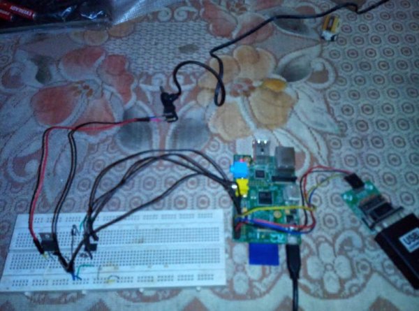
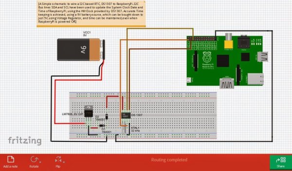
What i have tried with this blog is to show how,we can add a RTC, say DS1307 with RaspberryPi, register it with the Linux Kernel, and the methods involved. First, we need to put a circuit in a Breadboard using any of these RTC ICs. A breadboard, few single strand wires, DS1307 and a 32.768 kHz, crystal oscillator.
is close to 50 Mb.( http://fritzing.org/download/ )
at all times, while the RaspberryPi, will be powered as per user convenience, at any Time. When, the RaspberryPi powers
up, it should detect the DS1307 and register its module, rtc-ds1307, with the kernel, and create a Device node in the /dev
directory, namely as ‘rtc0' or ‘rtc1'. Subsequently, RaspberryPi, should read the Date and Time from the EEPROM of DS1307,
and after startup, and should show the current time. This, is the aim of this small exercise.
After, connecting the above circuit, we will check if RTC module,DS1307 is present in the kernel image or not. If, not build
the kernel with the following changes in the config file, as given below:
#
# I2C RTC drivers
#
CONFIG_RTC_DRV_DS1307=m
CONFIG_RTC_DRV_DS1307=y
For, convenience, one can refer the following config file that i have attached in the form of .txt here
(https://drive.google.com/file/d/0B6Cu_2GN5atpMzUxOXJCSmlzOEk/edit?usp=sharing), copy,
make the above change,and place it inside ‘/arch/arm/configs' directory of the Linux Kernel Source.
After, this start the usual cross-compilation of the Kernel source, using the following steps:
‘kernel.img', and copy the built Kernel image in the ‘/boot' partition of the RaspberryPi. After, this
add the below lines in ‘/etc/modules' file, which specifies the modules to be loaded at boot time:
# /etc/modules: kernel modules to load at boot time.
#
# This file contains the names of kernel modules that should be loaded
# at boot time, one per line. Lines beginning with “#” are ignored.
# Parameters can be specified after the module name.
i2c-dev
i2c-bcm2708
rtc-ds1307
snd-bcm2835
Now, that, RTC, DS1307 Module is present in the Linux Kernel,the next step would be to install
i2c-tools which will help us detect if any I2C capable device is using the I2C Bus of RaspberryPi and
the corresponding device address, using i2cdetect.The sources for i2c-tools can be downloaded from:
http://ftp.acc.umu.se/debian/pool/main/i/i2c-tools/
Download ‘i2c-tools_3.1.0.orig.tar.bz2', and copy it in the SD Card of your RaspberryPi, in some
location, say. ‘/home/pi'. After, booting up RaspberryPi, go to the location, ‘/home/pi', and extract the
source for i2c-tools.
#tar -xvzf i2c-tools_3.1.0.orig.tar.bz2
After, extracting the source, a folder by ‘i2c-tools_3.1.0' will be created. Build the i2c-tools sources
from this extracted source.
peripheral connected to I2C Bus of RaspberryPi. After powering on and connecting, the RTC circuit
to RaspberryPi, we power on the RaspberryPi and run i2cdetect for i2c-0 and i2c-1.
#i2cdetect -y -a 0
#i2cdetect -y -a 1
The Above figure shows that ds1307 is detected on I2C-1 Bus, on address 0x68, however ‘UU' means that the device is
busy, and is not available. To, detect the DS1307 RTC at RaspberryPi startup, a few changes would be required in the
RaspberryPi startup files. So, to start looking at them, lets look into the file'/etc/rc.local ‘, in the Root File System
partition.
Add the following lines, at the beginning, of the file, ‘/etc/rc.local':

As, shown in the figure above, in the ‘rc.local' file,we have added the following lines, which will set the DS1307 to use
I2C Bus with device address 0x68. Also, we have removed the default fake HWClock, which is governed by Kernel
timer mechanism, since now we will set the HWClock as being updated externally using RTC.
After this, in the boottime parameters and bootargs of RaspberryPi, we have to add the following argument:
rtc.i2c=ds1307,1,0×68
In the file ‘/boot/cmdline.txt' in the Boot Partition,the above lines would be added in the following way:
dwc_otg.lpm_enable=0 rtc.i2c=ds1307,1,0×68 console=ttyAMA0,115200 kgdboc=ttyAMA0,115200 console=tty1
root=/dev/mmcblk0p2 rootfstype=ext4 elevator=deadline rootwait
After, this power in the RTC DS1307 circuit, first and after that power up RaspberryPi. The RaspberryPi boots up
and starts successfully. Now, check, the ‘dmesg' logs using:
#dmesg | tail
The following output should be displayed, which shows that DS1307 has been registered as a Device node, ‘rtc0'
[ 22.999268] rtc-ds1307 1-0068: rtc core: registered ds1307 as rtc0
[ 22.999309] rtc-ds1307 1-0068: 56 bytes nvram
[ 22.999363] i2c i2c-1: new_device: Instantiated device ds1307 at 0x68
Check, the ‘/dev' directory, and we can see a device node ‘rtc0' has been created successfully.
For more detail: Interfacing RaspberryPi with DS1307,I2C based Real Time Clock

