
Race the Raspberry Pi!
We wanted to see if we could control the speed of a car via the internet. When we looked for tips on where to start we found that quite a few people had had a crack at it, but the documentation was all over the place.
So, we figured it out and pieced it all together in one example below. We plugged the system into dataplicity, and now we can set an optimum steady speed on a smart phone!
dataplicity for the win!
Prerequisities
To run this you will need:
- SCALEXTRIC set including track and car (not DIGITAL)
- Power supply 12-14VDC capable of 1-2A
- Spare SCALEXTRIC hand-held controller (likely will be sacrificed)
- Raspberry Pi Model B, or Model A with WiFi
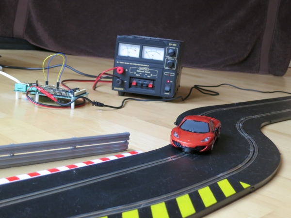
- Gertboard – this is an expansion board costing about £30 when we looked that is well suited to connecting your Raspberry Pi to your IoT; you can see one attached to a Pi below. You’ll need it because you’ll use only the motor controller output via Raspberry Pi PWM output.
- A free dataplicity account
Caution! Scalextric digital sets:
We don’t have a SCALEXTRIC digital set so have no way to know if this project will work with one. Accordingly we suggest you try it only if you know what you are doing.
Connect the wiring
You do not need the SCALEXTRIC power supply for this project, so just disconnect it for now. We will be connecting our own power supply.
Disassemble the hand-held SCALEXTRIC controller (there are three screws needed to open it). There are three coloured wires on the end of the cabling inside the controller: red, black and green. Each wire with have a tiny flat round plug on the end. You will later screw these wires into the Gertboard headers which are too narrow for the flat round plugs on the end so you may as well cut them off now rather than fiddle about trying to save the controller. The green wire will carry current during operation but is not needed, so tape it up with some electrical tape to keep it safe.
Prep the Gertboard, noting the correct orientation:
- Fit a jumper to the top two pins on J7 (it won’t work without this, we tried it).
- Connect GP18 on J2 to MOTA on J5.
- Connect GP17 on J2 to MOTB on J5.
- Connect your 12-14V DC power supply Ground to the ground pin on J19 (marked with an upside down T symbol).
- Connect the +ve terminal of your 12-14V DC power supply to MOT+ on J19.
- Connect the black wire of your SCALEXTRIC controller cable to MOTA on J19 and the red wire to MOTB on J19.
- Connect the other one to the lane (track) where you anticipate running your car.
That’s the wiring done.
Set up the new Raspberry Pi software
If you don’t already have a dataplicity account, get a free dataplicity account here.
To set up your Pi, follow the usual dataplicity getting started guide at http://dataplicity.com/get-started/raspberry-pi/ to connect your Pi to dataplicity, and to register a device class generating a sine wave.
You’ll need two additional packages installed at this point: python-dev and wiringpi. These are needed to interface with the Gertboard via PWM.
You must install python-dev first, or wiringpi will fail to install. Type in at the LXTerminal on your Pi:
pi@raspberrypi ~ $ sudo apt-get install python-dev
Then, type in:
pi@raspberrypi ~ $ sudo pip install wiringpi
You’ll see:
Downloading/unpacking wiringpi
Running setup.py egg_info for package wiringpi

Installing collected packages: wiringpi
  Running setup.py install for wiringpi
    building '_wiringpi' extension
    gcc -pthread -fno-strict-aliasing -DNDEBUG -g -fwrapv -O2 -Wall -Wstrict-prototypes -fPIC -I/usr/include/python2.7 -c WiringPi/wiringPi/lcd.c -o build/temp.linux-armv6l-2.7/WiringPi/wiringPi/lcd.o
    gcc -pthread -fno-strict-aliasing -DNDEBUG -g -fwrapv -O2 -Wall -Wstrict-prototypes -fPIC -I/usr/include/python2.7 -c WiringPi/wiringPi/piHiPri.c -o build/temp.linux-armv6l-2.7/WiringPi/wiringPi/piHiPri.o
    gcc -pthread -fno-strict-aliasing -DNDEBUG -g -fwrapv -O2 -Wall -Wstrict-prototypes -fPIC -I/usr/include/python2.7 -c WiringPi/wiringPi/piThread.c -o build/temp.linux-armv6l-2.7/WiringPi/wiringPi/piThread.o
    gcc -pthread -fno-strict-aliasing -DNDEBUG -g -fwrapv -O2 -Wall -Wstrict-prototypes -fPIC -I/usr/include/python2.7 -c WiringPi/wiringPi/wiringPiFace.c -o build/temp.linux-armv6l-2.7/WiringPi/wiringPi/wiringPiFace.o
    gcc -pthread -fno-strict-aliasing -DNDEBUG -g -fwrapv -O2 -Wall -Wstrict-prototypes -fPIC -I/usr/include/python2.7 -c wiringpi_wrap.c -o build/temp.linux-armv6l-2.7/wiringpi_wrap.o
    wiringpi_wrap.c: In function âinit_wiringpiâ:
    wiringpi_wrap.c:4456:21: warning: variable âmdâ set but not used [-Wunused-but-set-variable]
    gcc -pthread -fno-strict-aliasing -DNDEBUG -g -fwrapv -O2 -Wall -Wstrict-prototypes -fPIC -I/usr/include/python2.7 -c WiringPi/wiringPi/wiringPi.c -o build/temp.linux-armv6l-2.7/WiringPi/wiringPi/wiringPi.o
    gcc -pthread -fno-strict-aliasing -DNDEBUG -g -fwrapv -O2 -Wall -Wstrict-prototypes -fPIC -I/usr/include/python2.7 -c WiringPi/wiringPi/wiringSerial.c -o build/temp.linux-armv6l-2.7/WiringPi/wiringPi/wiringSerial.o
    gcc -pthread -fno-strict-aliasing -DNDEBUG -g -fwrapv -O2 -Wall -Wstrict-prototypes -fPIC -I/usr/include/python2.7 -c WiringPi/wiringPi/wiringShift.c -o build/temp.linux-armv6l-2.7/WiringPi/wiringPi/wiringShift.o
    gcc -pthread -shared -Wl,-O1 -Wl,-Bsymbolic-functions -Wl,-z,relro build/temp.linux-armv6l-2.7/WiringPi/wiringPi/lcd.o build/temp.linux-armv6l-2.7/WiringPi/wiringPi/piHiPri.o build/temp.linux-armv6l-2.7/WiringPi/wiringPi/piThread.o build/temp.linux-armv6l-2.7/WiringPi/wiringPi/wiringPiFace.o build/temp.linux-armv6l-2.7/wiringpi_wrap.o build/temp.linux-armv6l-2.7/WiringPi/wiringPi/wiringPi.o build/temp.linux-armv6l-2.7/WiringPi/wiringPi/wiringSerial.o build/temp.linux-armv6l-2.7/WiringPi/wiringPi/wiringShift.o -o build/lib.linux-armv6l-2.7/_wiringpi.so

Successfully installed wiringpi
Cleaning up...
Next, load the kernel module for the device:
pi@raspberrypi ~ $ sudo modprobe spi_bcm2708
At this point you should have access to the Pi’s PWM output, and through this to the Gertboard motor control output and to the SCALEXTRIC track.
For more detail: Internet controlled SCALEXTRIC