
A Tour of the Pi Zero
It's Thanksgiving 2015 – the turkey's brining, the potatos not-yet-mashed…and from Pi Towers the call goes out A NEWPI IS BORN! LONG LIVE THE PI!
The Pi Zero – the smallest, thinnest, most-affordable Pi ever. So much so, it comes free with every issue of MagPi #40.
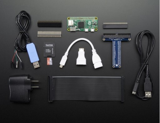
Want to get your own? Pick up a Raspberry Pi Zero starter kit, basic kit or just the bare computer board at the adafruit shop. (https://adafru.it/jEe)
What's new? What's different?
Wow a new Pi – so exciting! The Pi Zero is the smallest, most affordable Pi ever. Wonder what's new & different? Let's check it out!
Size
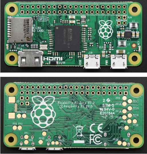
First up, the Pi Zero is small and thin 65mm long x 30mm wide x 5mm thick (31mm if you include the little sticky-out bits of the microUSB jacks)
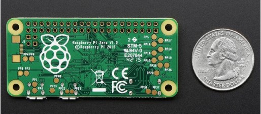
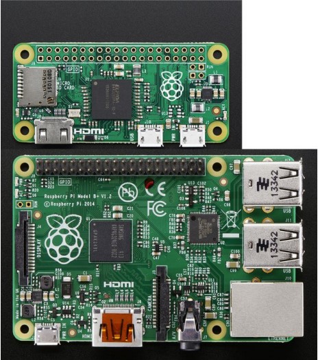
Way smaller than the Pi 2 or B+ and even smaller than the A+, its 60% the size of the A+: same length, and about half the width:
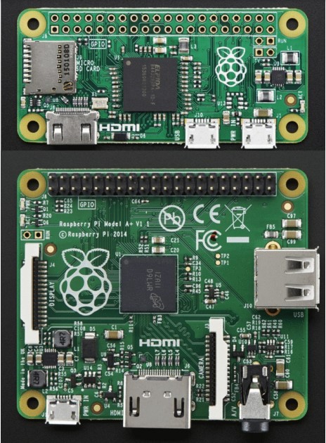
And about 40% the size of the Pi 2 or B+
Processor and Speed
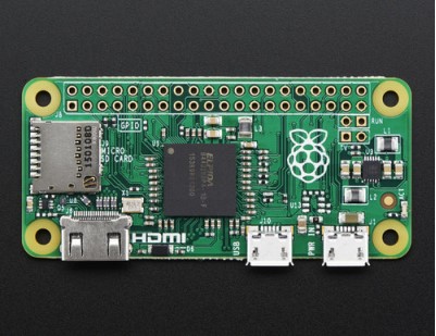
To keep the Pi Zero low cost, the processor and RAM are kept pretty basic. Instead of the Pi 2's zippy quad core ARM v7, we're back to a single-core 1GHz ARM (same processor in the Pi Model B+ and A+). We also have 512 MB of RAM with a ‘package-on-package' setup. The chip shown here:
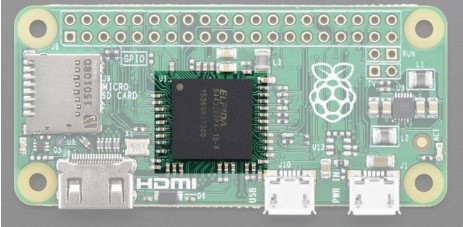
Is the RAM that is sitting on top of the main processor.
For maker and hacker projects, this isn't a big deal. You're essentially going to get the same performance as the Pi A+or B+. If you're looking for something that can do some more serious processing, check out the Pi 2
(http://adafru.it/2358)
Micro SD Card Holder
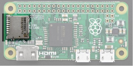
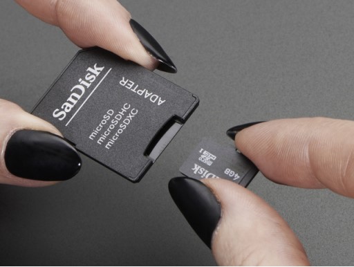
Not much has changed here, we're still going with MicroSD for size and ease of use (they're the most common card size these days!) This time the card holder is up top and is push-pull style not push-push. Honestly, I prefer it this way since you wont accidentally ‘push-pop' the card out
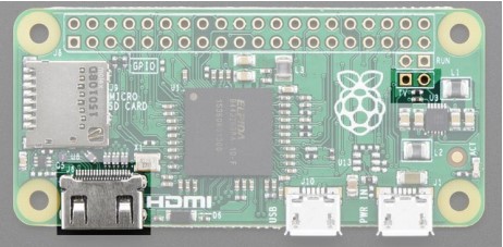
Video Out
HDMI Video is still available, you'll want to use a Mini to Standard HDMI adapter (http://adafru.it/2819) to connect an HDMI cable. There's no 3.5mm jack with composite out, however you can get PAL or NTSC out via two 0.1″ pads.
We've got a bigger write-up here about Pi Zero video outputs.(https://adafru.it/jEf)
Audio out
No analog audio out, but if you connect HDMI to a monitor with speakers you will get HDMI digital audio. It's also possible to hack analog audio out with a few passive components, see our more detailed look at Pi Zero audio output options. (https://adafru.it/jEh)
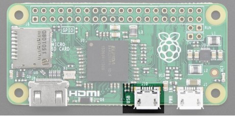
USB Port
Like the Pi Model A+, the Pi Zero does not have a USB Hub built in which means you get one USB port! Moreover that USB port is not a standard type A port, instead it is a ‘USB On-The-Go' port
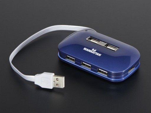
If you need to connect multiple USB devices, a simple USB hub will do what you need. A powered hub is even
better (http://adafru.it/961), and will let you power high-current USB devices like WiFi adapters and even external USB
hard-drives.
As a bonus you can power the Pi Zero from the hub (the power cable does not pass any data) – just plug the power micro USB cable into one of the ports.
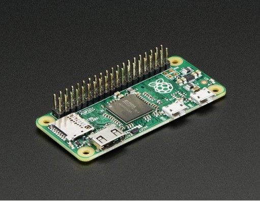
GPIO Header
To keep the Zero as simple and small as possible, the ‘normal' GPIO header spot has been left blank! Normally, a 2×20 male header is soldered in there (http://adafru.it/2822). While you could grab one of those and solder them in, the empty spot has a lot of potential. For example, you can solder in right-angle socket header, and turn the Pi Zero it a sort of ‘daughter card'
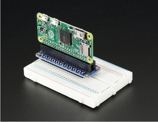
We've got more ideas and suggestions on our GPIO header detail page (https://adafru.it/jEi)
Setting up your SD card
Before you can power up your Pi Zero, you will need to program in the SD card with anOperating System
Much like your computer has Windows, Mac OS X or Linux on it to make it run, the Raspberry Pi needs something to help it boot and run software. That software is Raspbian Linux (a flavor of Debian Linux). You can check out our tutorial on What Is Linux if you're curious to learn more (https://adafru.it/jDZ) If you just want to get rockin, grab the latest (https://adafru.it/fQi) Raspbian Jessie operating system from the Raspberry Pi downloads page (https://adafru.it/fi7)Just click the button below!
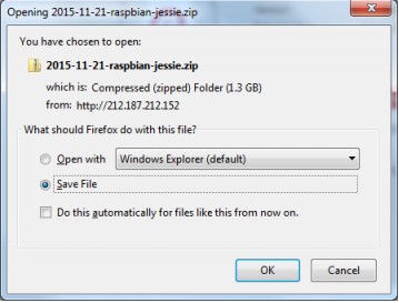
Once downloaded, unzip the zip file, the full image is about 4.5 Gigabytes.Next up grab your SD or micro SD card reader and plug it into your computer
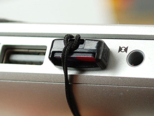
Now follow our guide for Windows (https://adafru.it/jE4) or Mac OS X (https://adafru.it/jE5) to burn the image

Once you're done, plug the micro SD card into the slot indicated. It will fit snugly in place but you won't hear or feel a ‘click'
Making an SD Card – Using Windows
We really like using Etcher for burning SD cards. Works great on any version of Windows, won't over-write your backup disk drive, and can handle compressed images so you dont need to unzip them!
Step 1.
Download Etcher from: https://etcher.io/ (https://adafru.it/sNF)
Step 2.
Run the downloaded app to install!
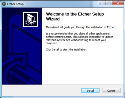
You can start immediately, doubleclick the Etcher desktop icon, or select it from the Start menu
Step 3.
Eject any external storage devices such as USB flash drives and backup hard disks. This makes it easier to identify the SD card. Then insert the SD card into the slot on your computer or into the reader.
Step 4.
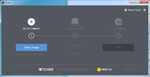
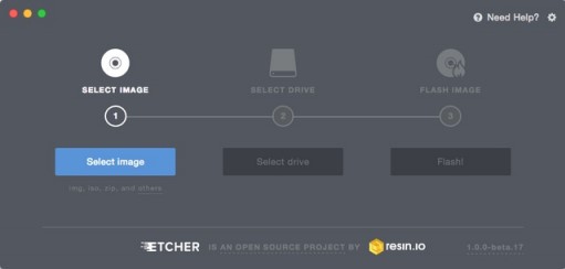
Run the Etcher program
This will launch the following application.
Step 5.
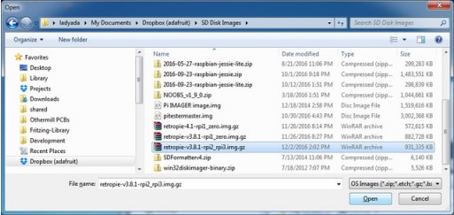
Select the image file by clicking Select Image you can select a compressed file such as a .zip or .gz
Step 6.
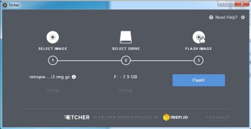
Etcher will automatically try to detect the SD drive, check the size to make sure its the right one
Then click Flash!
Check that you have the right device, as it will be reformatted, and then click Install.
It will take a few minutes to install, but once the SD card is ready, you will see the following.
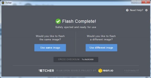
That's all there is to it. Your SD card is ready for use in your Raspberry Pi.
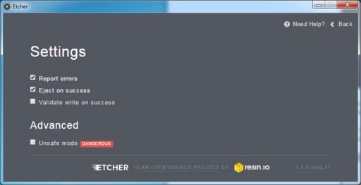
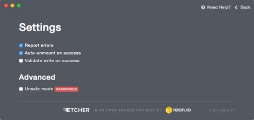
Faster writes
If you burn a lot of cards, speed it up by turning offValidate write on success
Making an SD Card – Using a Mac
We really like using Etcher for burning SD cards. Works great on Mac OS X 10.9 or later, won't over-write your backup disk drive, and can handle compressed images so you dont need to unzip them!
Step 1.
Download Etcher from https://etcher.io (https://adafru.it/sOe)
https://adafru.it/sNF
https://adafru.it/sNF
Step 2.
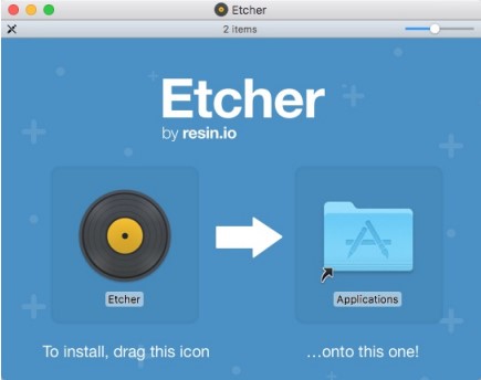
Open the downloaded disk image and drag the Etcher application to the Applications folder. You can then eject the disk image.
Step 3.
Eject any external storage devices such as USB flash drives and backup hard disks. This makes it easier to identify the SD card. Then insert the SD card into the slot on your computer or into the reader.
Step 4.
Run the Etcher application.
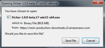
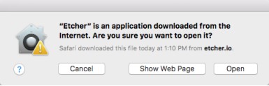
The first time you run Etcher you’ll be asked to confirm the download. Click “Open” to continue.
This will launch the Etcher application…
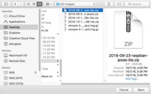
Step 5.
Select the SD card image file by clicking Select Image. You can choose a compressed SD image file such as
a .zip or .gz or an uncompressed .img, it’s all good!
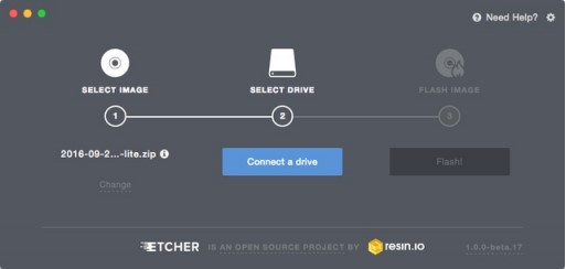
Step 6.
Etcher will automatically try to detect the SD drive. If you don’t have an SD card currently inserted, you’ll be prompted to connect one.
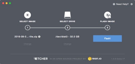
Check the disk size to make sure its the right one, that it’s not overwriting your main drive or anything nasty.
Then click Flash! A-ah!
Etcher will work for a few minutes to “burn” the SD image to the card. You’ll see a progress bar as it works. This is about the time you’ll wish you’d splurged on a high-speed card. Once the SD card is ready, you will see the following:
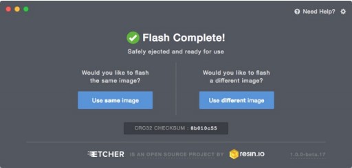
The card will be unmounted automatically, so you can pull it out now and use it in your Raspberry Pi.
Faster Writes
If you find yourself burning a lot of SD cards, you can speed things up by clicking the gear icon at the top-right, then turn off the “Validate write” option. I’ve written hundreds of cards and only had one fail validation.
Video Outputs
The Raspberry Pi chipset was originally designed to be a HDMI/graphics co-processor for mobile devices. For that reason, it has quite a bit of ‘HDMI horsepower' and can, despite it's small size, play 1080p video at full screen.
HDMI Video Out
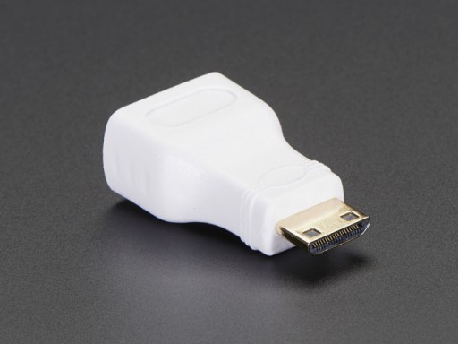
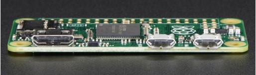
The easiest & fastest way to get video going is to connect up an HDMI display (https://adafru.it/jsb). We have a ton of options, and any HDMI display size from 640×480 up to 1920×1080 will work. The Mini HDMI port is conveniently labeled and shown below:
To connect an HDMI device, you'll need 2 things, aMini HDMI to HDMI Adapter(http://adafru.it/2819) and an HDMI Cable (http://adafru.it/608)
The HDMI cable is pretty straight-forward to understand, and you can get one anywhere. The HDMI adapter is required because the Pi Zero does not have a standard size HDMI port, instead the port is slimmer and smaller to keep the Zero petite. The adapter is pretty straight forward to use – plug it into the Pi Zero and the port is now large enough for any standard HDMI cable
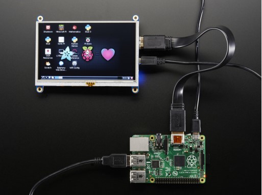
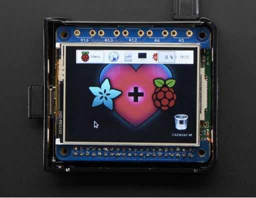
PiTFT Video
Even though it is ‘half size' of the A+, you can still use any of our PiTFT's on the Pi Zero (https://adafru.it/jE7) You can use any size from our 2.2″ 320×240 PiTFT HAT, up to our 3.5″ Touchscreen 480×320.
Before you can plug in a HAT or PiTFTyou'll need to solder in the 2×20 male header (http://adafru.it/2822)
Then follow the tutorial for the PiTFT of your choice! Be sure to pick the Jessie install image
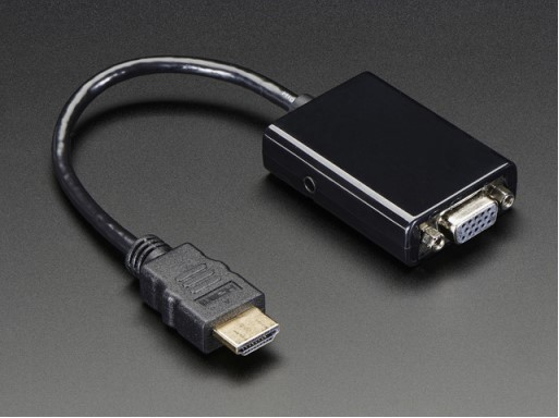
VGA Video Out
This one is pretty easy, just use the HDMI adapter above, and anHDMI to VGA adapter (this also has the benefit of giving you an audio output) (http://adafru.it/1151)
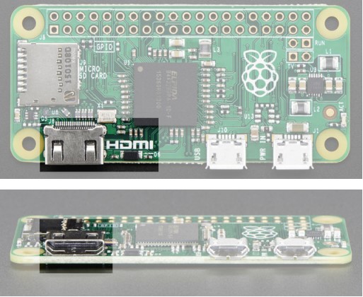
NTSC/PAL Composite Video
OK so you want TV video? Maybe for one of our very tiny composite video screens (https://adafru.it/jE8)?
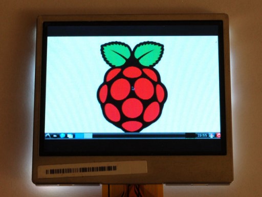
Well, the quality is not going to be nearly as nice as with VGA or HDMI but you can do it. Find the two pads markedTV on the ‘Zero
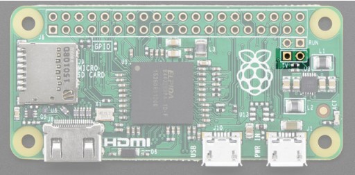
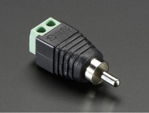
The hole on the left, nearest to the TV text, is the signal (+) line, the pin to the right of it is the ground (-) line. Solder two wires to these pads and connect them to an RCA Jack (http://adafru.it/2792) like this one
Make sure to not have HDMI plugged in, it should auto-switch to TV out. If you have somehow set your Pi for HDMI out only, plug your HDMI screen back in, or use a console cable to connect and log into the Pi. Then run sudo raspi-config at a command line to set video output to composite!You'll also want to tweak your Pi to use composite in the nicest resolution possible (https://adafru.it/diN)
Audio Outputs
Uh, well, there aren't any! That's right, to keep the Pi Zero small and low cost, the headphone audio filter isn't included You can still get digital audio out via HDMI so if you plug it your Pi into a monitor with speakers, that will work fine.
How to Add Audio Outputs to your Pi Zero
Hey, wanna do the below but with step-by-step instructions? We wrote a tutorial! Click here to do the thing @ https://learn.adafruit.com/adding-basic-audio-ouput-to-raspberry-pizero (https://adafru.it/jZD)
How Other Pi's Create Audio
GPIO #18 is also known as PWM0 and in the original Pi was coupled with a very basic RC filter to create the audio output:
If you don't mind getting a few 150 and 270 ohm resistors, and two each of about 33nF (also known as 0.033uF) and 10uF capacitors, you can basically recreate those two filters.
Now all you need is access to PWM0_OUT and PWM1_OUT, which are…on GPIO #40 and #45 and are not brought out on the Pi Zero. Tragedy? Give up? No! You can get to PWM0 on GPIO #18 (ALT5) and PWM1 on GPIO #13 (ALT0) or GPIO #19 (ALT5) – see the full list of pins and alternate functions here (https://adafru.it/jEa)
You can do that by adjusting the device tree overlay to change the PWM audio pins from pins #40 and #45 (which are not accessable) to pins #18 and #13 This very nice Pi forum thread will tell you how! (https://adafru.it/jEb)
See here for a program that will let you set the alt forms of GPIO pins (https://adafru.it/jEc)
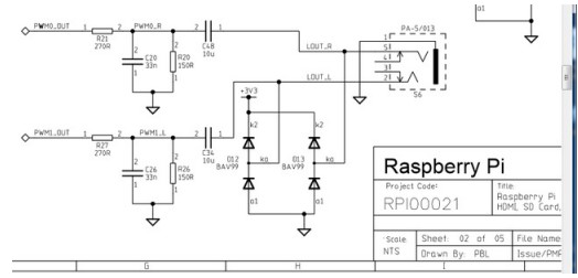
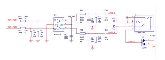
If you want a higher quality audio output, the B+ and Pi 2 use this schematic – it has a driving buffer on the audio PWM lines for better current drive and it uses a cleaner 2.5V reference for better quality audio.
GPIO header options
The most intriguing difference for hackers and makers is that the Pi Zero does not come with the soldered GPIO header. Partially this is to save cost, but it also allows the Pi Zero to be very thin and gives you the option of embedding it easily into a project box.
Cons:
You have to solder in the header to use Pi HATs and Pi toppers
Pros:
You can practice your soldering!
Can skip the GPIO header to keep the Pi Zero super slim
Solder wires directly into the GPIO pads, use only what you need
Try different, exotic headers such as right angle or socket header
Go Classic with 2×20 Male Header
Like blue jeans and Coca-Cola, the 2×20 male header is the classic option. (http://adafru.it/2822)
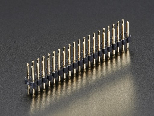
Once soldered in, you can plug in any HAT or topper. The pinout is completely identical to the 2×20 headers on the Pi 2 and Pi A+ & B+
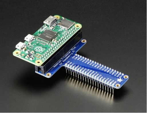
Or 2×20 Female Socket Header
This one is interesting, if you solder in a 2×20 female socket header(http://adafru.it/2222)
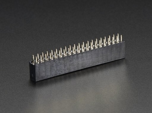
and attach it upside down you can plug it right into a T-Cobbler!
Advanced 2×20 Right-Angle Female Socket Header
Or, take it even more extreme with 2×20 right angle female header (http://adafru.it/2823)
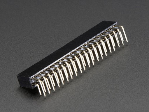
Now you can stick it into a Cobbler or T-Cobbler and it will sit sort of like a computer daughtercard!

Is There Even Life?
You can skip this section unless you have reason to believe your Pi Zero isn't alive. The Pi Zero doesn't have much in the way of blinky LEDs to give you a warm fuzzy that it's doing anything or even alive. And if the GPU doesn't find a valid OS image, it doesn't even turn on the green ACT LED and looks totally dead. Typically this just means something is up with the SD card. Bad card. Bad image. Out of date image. Whatever. It does not mean the Pi Zero is dead.
Here's how to run a sanity check to verify if the Pi Zero is OK.
- (taken from here (https://adafru.it/upa) and also provided here (https://adafru.it/vIe))
- Take your Zero, with nothing in any slot or socket(yes, no SD-card is needed or wanted to do this test!).
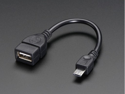
- Take a normal micro-USB to USB-A DATA SYNC cable (not a charge-only cable! make sure its a true data sync
- cable!)
- Connect the USB cable to your PC, plugging the micro-USB into the Pi's USB, (not the PWR_IN).
- If the Zero is alive, your Windows PC will go ding for the presence of new hardware & you should see “BCM2708 Boot” in Device Manager.
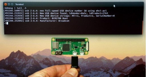
- Or on linux, run sudo lsusb or run dmesg and look for a ID 0a5c:2763 Broadcom Corp message. If you see that, so far so good, you know the Zero's not dead.
Below is a Pi Zero connected to a Linux computer via a USB cable and the resulting dmesg output.Note: there is no SD card installed, USB cable is in USB port, and there are no lights.
Here's what our Windows machine showed:
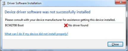
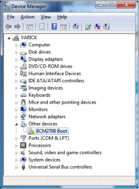
Looks dead, but it's not.