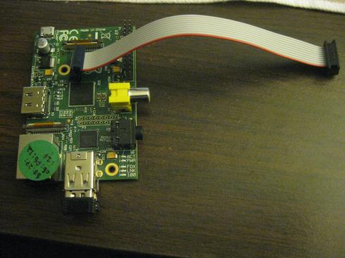
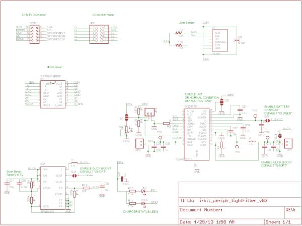
Here are some first passes at a Raspberry Pi shield design. I don't quite yet know what I'm doing, but here's the rough idea I'm aiming at. I'm not sure how sensible it is, so I'd love to get any feedback!
It'd be nice to have a device that: – controls a filter switcher motor for rapid switching between filters – has both VIS and IR light sensors, to calibrate camera readings – allows for several additional sensors to be designed and plugged in (temperature, humidity, soil moisture, etc) – operates on battery power

It'd be nice to have a device that:
- controls a filter switcher motor for rapid switching between filters
- has both VIS and IR light sensors, to calibrate camera readings
- allows for several additional sensors to be designed and plugged in (temperature, humidity, soil moisture, etc)
- operates on battery power
Further: we'd like to be able to place some of the sensors (e.g. the light sensor) in arbitrary orientations — we want it to be getting a good reading, and not be obscured by other structures in our device (or the device case).
I started thinking about how to make this work on a Raspberry Pi, and I realized that one approach to this problem had some possible overlaps with an Arduino-compatible platform I'd been working on with friends, recently. We've been trying to come up with a slightly re-designed Arduino-compatible board that has a “port” structure allowing for a (somewhat) “plug and play” sensor architecture. We'd already begun to design the boards and start in on the peripherals, so I figured I'd leverage some of that work, here. Still not sure if it's the right approach, but in the spirit of throwing crazy ideas together and seeing what sticks …

I also added eight “OLM-style connectors” (we've been calling the Arduino-compatible prototype I mentioned above the “Open Lab Monitor (OLM)” — but we could henceforth refer to it as a “PL Connector”, if folks like the interface!). Each of these eight connectors is a 2×5 arrangement of pins with connections to:
- 3.3 V
- ground
- SPI
- I2C
- two digital I/O pins
- one analog I/O pin
For more detail: ircam raspberry pi shield — first steps

