
This blog is dedicated to electronic projects and software due to the author’s enthusiasm for these activities. The main aim is to share to other enthusiasts the experience in electronic design of the author who disclaims all responsibility. All presented projects are realized and fully tested by the author who intends to preserve the intellectual property of the projects or information, whose utilization is intended only for non-professional purposes.
An isolated analog input for Arduino
by Giovanni Carrera, rev. 28/05/16
A voltage to frequency converter can realize an opto-isolated analog input for Arduino or other microcontroller systems. This circuit is particularly suitable for industrial control plants with 4-20mA sensors.
Introduction
The signals from field sensors can be affected by noise generated by power surges, lightning strikes or other EMI (Electromagnetic Interference) sources and also by ground potential differences. One method to avoid most of these problems is to use a complete isolation from the field.
The isolation of an input sensor will require a separate power supply to power the field device and the circuit that realize the insulation itself.
In the 80s, when the microcontrollers hadn’t digital to analog converters (ADC) integrated, I had designed a system with voltage to frequency converters to achieve high-resolution analog inputs and an easy true isolation with the field sensors. Only drawback was the low sampling rate, but usually high frequencies aren’t required in industrial plants.
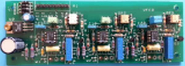
The following figure shows a three channels board that I designed many year
he circuit
So I think up to use this circuit also with Arduino. The diagram of Figure 2 shows the circuit that accepts an input voltage from about 20mV to 5V or a current of 4 to 20 mA (with the jumper W1 inserted). The two resistors in parallel R2 and R3 give a value of about 250 ohms, in order to have 1V to 5V for 4mA to 20mA input.
Just three wires and a resistor are required to connect the circuit to the Arduino Uno. The output of the opto-coupler should be connected to the digital input D5 with a pull-up 2.2kW resistor connected to the +5V of Arduino.
s ago for a 6502 control system.
For more details: An isolated analog input for Arduino