
Note: I only write about what I know. Although there are many Arduinos and Arduino type products, I only have experience with the Arduino Uno Rev3. Likewise, the only Atmel microcontroller I know is the ATmega328P.
A Little Background (well not so little)
I have Atmel ATmega328P microcontrollers on two devices: An Arduino Uno (Rev 3), and a Gertboard. The Gertboard connects to, and is programmed by, my Raspberry Pi. In both cases the microcontroller is in a socket, so is removable. I have developed applications for both where I needed to remove the ATmega328P and install it in another device. I use the Arduino IDE system to develop sketches on both the Arduino and the Gertboard/Raspberry Pi. There is more on the Gertboard at the end of this post.
I developed a camera remote control using the Gertboard and removed the programmed ATmega chip and installed it on a circuit board. The circuit board, a 434MHz transmitter, and a motion detector were mounted in a box. I reported on that project in this blog entry.
I am completing a project that uses both the Arduino and the Gertboard/Raspberry Pi. In this case, it is the sketch developed on the Arduino that must run on an ATmega328P that is removed from the Arduino. This project, that I will report on later, requires the ability to communicate with the ATmega328P once it is installed in my mobile device.
Both projects required me to program a new ATmega328P IC. However, you can not just insert a new chip on the Arduino or Gertboard and upload sketches to it. Out of the box, the microcontroller will not use the external 16MHz crystal of the Arduino or the 12MHz resonator of the Gertboard. It will use its internal 8MHz RC oscillator frequency reference and then divide that frequency by 8. The resulting clock frequency will be 1MHz.
In order to change the clock source, you must change the logic level of a couple of “fuse” bits. I use “” around the word fuse, because the term is actually a carryover from the time when ICs, like microcontrollers, had actual fuses. Each fuse would control the logic level of one bit. If the fuse was blown, the bit would be a 0, if not blown it would be a 1. You could always change a 1 to a 0, by blowing the fuse, but you had no way to change a 0 to a 1. If you wanted a 1, but programmed a 0, in error, you had to replace the chip. That is not the case today.
Now, “fuse” bits can be changed from 1 to 0 and 0 to 1 anytime. The ATmega328P has three, eight bit bytes of these “fuse” bits. They control different functions and leave the factory in a default configuration. In addition, there is a byte (8 bits) of lock bits. More on these later. To setup a new ATmega328P for the Gertboard, you run a program on the Raspberry Pi called avrsetup. All this program does is to use avrdude to set the lock bits and the fuse bits. It leaves all bits not concerned with the clock frequency to their default settings. The four bits that select the clock source are changed from “Calibrated RC Internal Oscillator” to “Full Swing Crystal Oscillator”. And, the divide by 8 function is turned off. Avrdude is like an operating system for the Atmel microcontrollers. All programming of the microcontrollers are done through avrdude even if you use the Arduino IDE.
For the Gertboard/Raspberry Pi, setting those fuse bits is all you have to do to use a new ATmetga328P. That is not the case with the Arduino. A new ATmega328P for the Arduino needs those same fuse bit changes and needs one more thing: a bootloader installed. What is a bootloader, and why doesn't the Gertboard need one?
When you upload a sketch to the flash memory of the ATmega328P, there are two direct ways. One is to use a parallel configuration, which I will not mention further (just going to forget it exists). The other is to use the chip's SPI (Serial Peripheral Interface) bus. This synchronous, serial, bus consists of four lines: SCK (Serial Clock), SS (Slave Select), MOSI (Master Out Slave In), and MISO (Master In Slave Out). I upload sketches to the Gertboard via the SPI bus. The Raspberry Pi is the Master, the ATmega328P on the Gertboard is the Slave.
Since the direct programming method is employed, no bootloader is necessary.
Atmel, in their wisdom, realized that not everyone would like to use the SPI bus, but would wish to use the more universal serial bus (or something else). The serial bus interface has several names such as RS232 and UART. It consists of several signals: TX (transmitted data) and RX (received data). The TX of the one device is connected to the RX of the other device, and RX of the first device is connected to TX of the second device. There are more signals, but, typically, they are not used. However, a signal, DTR (data terminal ready), for example, may be used to reset the ATmega328P. Once the ATmega328P is reset, it will start running any sketch loaded in flash from its beginning.
Atmel provided an area of flash memory for the user to install code allowing the rest of the flash memory to be uploaded via the serial bus. This code is the bootloader. For the ATmega328P, it can take up as much as 2 Kbytes of the 32 Kbytes of flash memory. The flash memory, not reserved for the bootloader, is the Application memory. Once the bootloader is loaded, it can load a new sketch into the Application memory via the RX and TX connections of the serial bus.
So, how do you get the bootloader loaded in a new ATmega328P? It requires hardware and software. Since a new ATmega328P has no bootloader, the bootloader must be installed from the SPI bus – the direct, primary, interface to the chip. That means you need an in-circuit programmer. There are inexpensive, commercial, units available like the USBtinyISP. They have USB on one end and the four SPI connections on the other end (SCK, SS, MOSI, and MISO), plus power and ground. They have a 6 pin ribbon cable and connector that plugs into your target device that contains the microcontroller chip you want to access. There is a standard 6 pin SPI configuration that receives the ribbon cable connector. My Arduino Uno has two of these 6 pin connectors, one for the ATmega16U2 and the other for the ATmega328P. You can install a new ATmega328P on your Arduino Uno and connect a programmer to it to upload the bootloader. But, I don't do that.
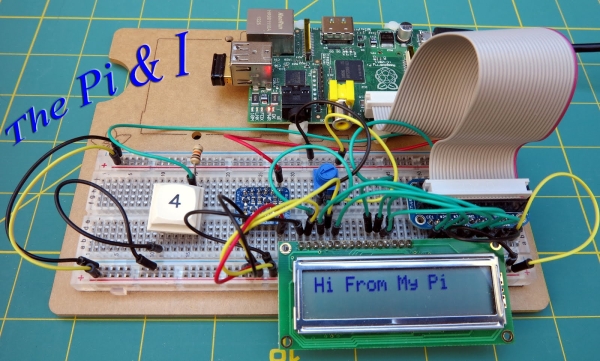
I have no experience with the aforementioned programmers so I will not discuss them. There is another programmer that works really well – and I have experience with that one. This programmer is the Arduino itself. You can't use it to load a bootloader on its own ATmega328P, but it can be used to install a bootloader on another Arduino's ATmega328P. However, I do a variation of that. I use the Arduino Uno to install the bootloader on an ATmega328P that is on a jig I made. This is the jig that is the subject of this blog post.
Now we need some software. There are two pieces of this. One piece is the bootloader itself. The Arduino IDE package has copies of the bootloaders. There are different bootloaders for the different ATmega devices and the different Arduinos. The other piece of software is the software to load the bootloader. This software is a sketch running on my Arduino Uno that is used as a programmer. This software must do several things. I have not studied this software to know how it works, but from my knowledge of the ATmega328P, I know it must do the following:
- Program the fuse bits to select the clock source to “Full Swing Crystal Oscillator” and turn off the clock divide by 8.
- Set the Lock bits to allow programming of the bootloader in the Boot Flash Section
- Set the fuse bits to the amount of flash memory devoted to the Boot Flash Section (up to 2 KBytes)
- Upload the bootloader program to the Boot Flash Section
- Set the lock bits so the Boot Flash Section can no longer be written to, protecting it from being overwritten.
There is one last point to consider before moving on to the details of my programming jig. Could there be an Arduino that programs the microcontroller directly over the SPI bus? Certainly. There are ICs that convert USB to SPI. That would eliminate the bootloader. We are forgetting one thing though: How do you communicate with a sketch? For example, a sketch that requires you to answer some questions before proceeding. The answer is the Serial Monitor. Access to the Serial Monitor is via the same interface the Arduino uses to upload sketchs – the same TX and RX connections to the ATmega328P.
For the Gertboard, the Serial Monitor button exists on the Arduino IDE running on the Raspberry Pi. However, it does not work. A separate connection to the ATmega328P's UART must be made. Consequently, the Raspberry Pi/Gertboard requires six signal connections: SCK, MOSI, MISO, SS, and TX and RX. The Arduino UNO only has two ATmega328P signal connections: TX and RX. For the Gertboard, I have to open a separate terminal window and run a terminal program to communicate with a running sketch. All-in-all, the loss of a little flash memory to the bootloader seems worthwhile.
Looking at the board layout, the ATmega328P sits in a 28 pin ZIF socket (all that green in the diagram). This allows an IC to be quickly inserted and removed. Check out the product page from Sparkfun.
The connector pins labeled SPI are for female – female jumper wires. This interface connects to the Raspberry Pi or to the Arduino Uno. Connections to the Raspberry Pi are to set the fusebits on an ATmega328P, and to load sketches developed on the Gertboard. The connections to the Arduino UNO are only to install a bootloader on an ATmega328P.
Note the interface labeled “FTDI”. This interface is used to upload sketches to an ATmega328P (must have the bootloader installed) that I have developed on my Arduino. In addition, it provides access to the Arduino IDE Serial Monitor, allowing us to communicate with a program running on the jig's ATmega328P. FTDI is the name of a chip manufacturer that makes USB to Serial ICs. The FTDI interface on my jig connects to a Sparkfun FTDI Basic breakout board. This small board has a mini USB on one end and a six pin female connector on the other that plugs directly onto my jig.
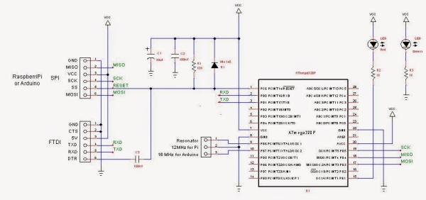
There is a three pin female connector labeled resonator. Since the Gertboard and the Arduino Uno operate on different frequencies, the connector allows a 12MHz resonator to be connected for the Gertboard sketches and a 16MHz resonator for the Arduino operations.
There are two LEDs on the jig. The green one lights whenever power is applied to the jig. 5V can come from the FTDI board or the Arduino Uno. The Gertboard will supply 3.3V. The red LED is a sanity check and is connected to PB1 of the jig (this corresponds to pin 9 of the Arduino). After loading a bootloader, I can check if I can upload a sketch to a new ATmega528P by running a version of Blink. Anytime I need to check the jig or my connections, I can program that red LED.
Parts List
- Prototype Breadboard PCB, half size: Adafruit 1609, $4.50
- ZIP Socket, 28 pin: Sparkfun PRT-09175, $2.95
- Right Angle Header Strip for FTDI and SPI: Mouser 571-9-103323-0, $2.24 for a strip of 40 pins
- ATmega328P Microcontroller: Mouser 556-ATmega329K-PU, $3.55
- Socket strip for Resonators: Digikey 1212-1125-ND, $3.89 for a strip of 64. Perfect socket for resonator pins
- 16 MHz Resonator: Mouser 520-ZTT1600MX, $0.50
- 12 MHz Resonator: Mouser 520-ZTT1200MX, $0.50
- Red LED – clear housing: Digikey C503B-RCN-CW0Z0AA1-ND, $0.15
- Red Green – clear housing: Digikey C503B-GCS-CY0C0791-ND, $0.24
- 10μF, 16V Tantalum capacitor: Mouser 581-TAP106K016CRW, $0.53
- 0.1μF 100V Ceramic capacitor: Mouser 1C20X7R104K100B, $0.18 ea.
- 1N4148 diode: Mouser 512-1N4148, $0.10
- 10KΩ Metal Film Resistor: Mouser 71-RN55D-F-10K, $0.10
- 1KΩ Metal Film Resistor: Mouser 71-RN55D1001F/R, $0.10 ea.
For more detail: Jig To Load a Bootloader and Upload Sketches To ATmega328P