
In electronics, a device is said to be a latching device if it maintains any particular fixed state even after removal of the input signal. The same also applies for electronic/electromechanical relays. Basically the electromechanical relays that are used today are of two types:
1. Non-Latching Relay : These relays are most widely used where energy consumption is basically not an issue.This type relay(s) comes back to its original state once the input signal is removed.
2. Latching Relay : These relays are mostly used in automobiles and are rarely used for basic prototyping needs.
Most of the relays which we use today are monostable relays, that means it has only one stable state and so it is called non-latching relays. You must have heard about N.O (Normally Open) and N.C (Normally Closed) terminals of a basic electromechanical relay. However these terminals which are present over the relay show that the electronic relay which we are using has only one stable state.
In this instructable I will show you how to use a non-latching relay as a latching bistable relay by designing a simple electronic module which is powered by an external power source. One can use this module for many other projects and it's intentionally made portable so that one can easily carry it around. Moreover it has many other useful features which provides it many additional functionalities.
To get a detailed idea of the working please watch the above video or click on the link below:
Step 1: Gather the Required Components and Tools.
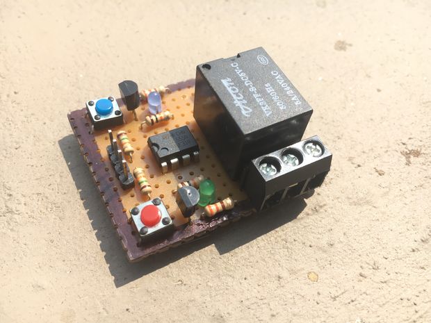
All the tools and components used to make this module can be easily bought from nearby local electronic shops.
COMPONENTS REQUIRED:
- 1x Small Size Perforated Circuit Board
- 1x 3 PIN PCB Mount Screw Terminal
- 1x 5V-DC 240V, 50-60Hz, 5A SPDT Relay
- 3x BC547 NPN Transistor
- 2x Small LEDs (Different colors are recommended.)
- 2x 330ohms Resistors
- 2x Momentary Push Button Switches (Different colors are recommended.)
- 1x 1N4007 General Purpose PN Junction Diode
- 1x NE555 Timer IC
- 4x Male Header Pins
- 3x 10Kohms resistors
- 2x 15Kohms resistors
TOOLS REQUIRED:
Soldering Iron
- Soldering Lead Wire
- Soldering Flux
- Multimeter with Probes
- A strong Adhesive
Step 2: The Circuit Diagram
The above shown picture is the circuit diagram of the relay module. All connection of components have to be done in exact same manner as shown in the picture.
The above circuit is an implementation of the NE555 timer IC as a Latch or 1-Bit Memory Cell. The Set (ON) and Reset (OFF) function of the attached relay can be controlled by either using the momentary push buttons as switches or it can be controlled via 5V logic inputs from the SET or RESET pin sides.
The the type of latch that we are using here is SR latch.
In the circuit diagram the pin jack J1 refers to the power inputs and logic controls of the module, whereas the pin jack J2 refers to the 3-PIN screw terminal outputs from the relay.
Read more: Latching Relay Module