
I2C Accelerometer Sample
We'll connect an I2C accelerometer to your Raspberry Pi 2/MinnowBoard Max/DragonBoard and create a simple app to read data from it. We'll walk you through step-by-step, so no background knowledge of I2C is needed. However, if you're curious, SparkFun provides a great tutorial on I2C.
This is a headed sample. To better understand what headed mode is and how to configure your device to be headed, follow the instructions here.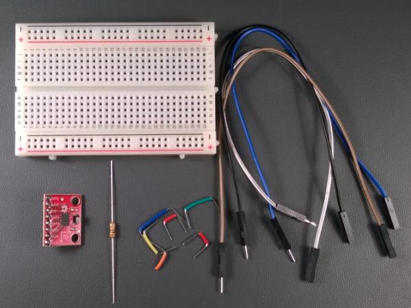
Load the project in Visual Studio
You can find the source code for this sample by downloading a zip of all of our samples here and navigating to the `samples-develop\Accelerometer`. Make a copy of the folder on your disk and open the project from Visual Studio.
Connect the I2C Accelerometer to your device
You’ll need a few components:
- an ADXL345 accelerometer board from Sparkfun with pin headers soldered on
- a breadboard and a couple of male-to-female connector wires
- If you are using a MinnowBoard Max, you’ll need a 100 Ω resistor (this is a workaround for a known I2C hardware issue)
Raspberry Pi 2
If you have a Raspberry Pi 2, we need to hook up power, ground, and the I2C lines to the accelerometer. Those familiar with I2C know that normally pull-up resistors need to be installed. However, the Raspberry Pi 2 already has pull-up resistors on its I2C pins, so we don’t need to add any additional external pull-ups here. See the Raspberry Pi 2 pin mapping page for more details on the RPi2 IO pins.
Note: Make sure to power off the RPi2 when connecting your circuit. This is good practice to reduce the chance of an accidental short circuit during construction.
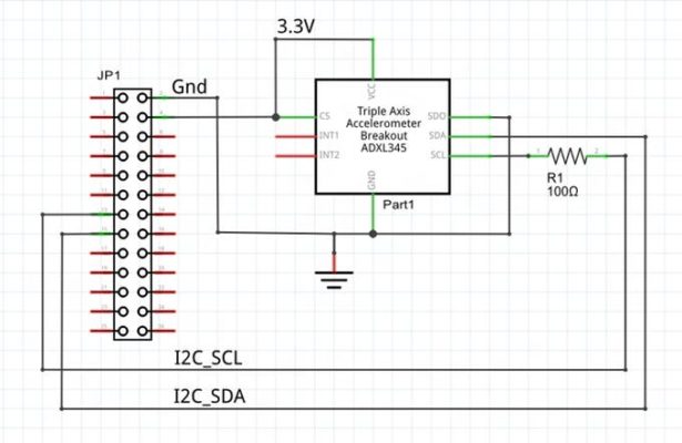
The ADXL345 breakout board has 8 IO pins, connect them as follows:
- GND: Connect to ground on the RPi2 (Pin 6)
- VCC: Connect to 3.3V on the RPi2 (Pin 1)
- CS: Connect to 3.3V (The ADXL345 actually supports both SPI and I2C protocols. To select I2C, we keep this pin tied to 3.3V. The datasheet contains much more information about the pin functions)
- INT1: Leave unconnected, we’re not using this pin
- INT2: Leave unconnected, we’re not using this pin
- SDO: Connect to ground (In I2C mode, this pin is used to select the device address. You can attach two ADXL345 to the same I2C bus if you connect this pin to 3.3V on the second device. See the datasheet for more details)
- SDA: Connect to SDA on the RPi2 (Pin 3). This is the data line for the I2C bus.
- SCL: Connect to SCL on the RPi2 (Pin 5). This is the clock line for the I2C bus.
MinnowBoard Max
If you have a MinnowBoard Max, we need to hook up power, ground, and the I2C lines to the accelerometer. Those familiar with I2C know that normally pull-up resistors need to be installed. However, the MBM already has 10K pull-up resistors on its IO pins, so we don’t need to add any additional external pull-ups here. See the MBM pin mapping page for more details on the MBM IO pins.
For more detail: Learn to use I2C Accelerometer