
Introduction to Physical Computing
1 Introduction
With over ten million units sold, the Raspberry Pi single board computer has become one of the most popular ways to learn computer science. Raspberry Pi s are ultra-low-cost, fully functional tiny computers. While there are many models of the Raspberry Pi , their purpose remains the same: to provide an affordable way to get hands on experience in the world of programming and electronics. This book focuses on providing examples that can be applied to real world applications of the board, such as controlling motors and recognizing sensor inputs. To do this requires use of ChIDE in conjunction with the Ch programming language.

Ch and ChIDE provide the ability to enter a line-by-line debugging mode which can be invaluable to the absolute beginner programmer and breed a greater intuition about how a program actually works. Some new projects are also added in order to highlight some of the salient capabilities of Ch, such as data plotting, and how they can be used for practical purposes in conjunction with a single board computer. Unlike a microcontroller, such as an Arduino, the Raspberry Pi runs on an actual operating system. For this book, the use of C-STEMbian, a variant of Raspbian, is required. This allows the board to be much more capable than the Arduino as it is a full computer; however, this also means that certain tasks are more complicated, such as analog inputs.
These projects and lessons provide a basic knowledge of how single board computers function with inputs (such as switches, knobs, temperature and light sensors) and outputs (such as LEDs, servos, motors). This book assumes that the user has the hardware from C-STEM Center or C-STEM industrial partner. As an expansion from previous C-STEM Center courses involving mathematic computing and robotics programming with the Linkbot, this book gives practical applications for programming and explores some of the inner-working of robotics programming. This will eventually lead a user to having the required knowledge to use the Input/Output (I/O) capabilities of a single board computer to create a self-driving, autonomous, vehicle. While a self-driving car is a classic goal for robotics, the possibilities for what a person can do with the power of a Raspberry Pi is only limited by their creativity. The goal of this book is to give the user enough knowledge to express their creativity with their own projects. This book assumes that the user has the Arduino Uno Starter Kit , Arduino Uno and Pi Sensor Kit , and Raspberry Pi Starter Kit which are available for purchase from Barobo, Inc. (http://www.barobo.com).


1.1 The Board

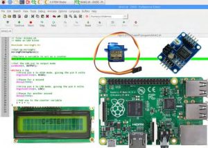
This is the Raspberry Pi, which is a single board computer. It contains a processor connected to many inputs and outputs, such as USB and ethernet. Additionally, there are many pins that perform various functions that will be used throughout the projects in this books. These I/O (input/output) pins are what make the Raspberry Pi such a powerful tool as they allow the user to perform many tasks. Ch code currently supports using a variety of Pi boards, including the newest Raspberry Pi 3 Model B and the Orange Pi. The differences between the spectrum of Pi boards are the processor size and power, the board’s physical size and layout, and the number of I/O pins. The Pi 3 Model B can be considered the standard board and will work for all of the projects presented in this book. While other boards may work for projects in this book, their layouts and capabilities can differ significantly.
Note: Before using the Raspberry Pi or any other variant, C-STEMbian operating system must be installed. The Pi is versatile in that in can be used on its own by connecting a monitor, or it can be accessed remotely via another computer either wirelessly or locally. For instruction on how all this can be done, see Chapter 23, or visit the the http://c-stem.ucdavis.edu/c-stembian/ page for up to date info.
1.2 The Breakout Board
It can be difficult to directly wire components to the pins of the Raspberry Pi . Because of this issue, a breakout board (or extension board) is often used. Think of the breakout board as simply a bridge between the Raspberry Pi and the breadboard, which is used for circuit building and will be discussed later. The ribbon cable forms a connection from each individual male pin on the Raspberry Pi to its own row of female pins on the breadboard. It also allows the ’5V’ and ’3V3’ power supplies to be available without any extra wiring, saving time and reducing troubleshooting. The
example used in this book is shown in Figure 1.3.
Like many of the attachments and accessories for the Raspberry Pi many variations of breakout boards exist. For this book, we will be using the model by Vilros, included the C-STEM Starter Kit. In effect, they all behave the same way,
although some do not include the power rails on the side.

1.3 The External Circuitry
Breadboards
The circuits required for the projects could be wired directly to the Raspberry Pi , but that would be very messy. That is why a breadboard is typically used for building temporary circuits. A breadboard contains a grid of sockets, like those on the Raspberry Pi , that can have wires plugged into them. Some pins in the rows of the breadboard are connected internally so plugging certain pins into certain rows will connect those wires. Breadboards allow for relatively complex circuits to be built and modified easily for testing and troubleshooting. A detailed explanation can be found in The Breadboard section in this chapter.

Resistors
As the simplest electrical component, resistors impede current flow and cause drops in voltage. Resistors are used in filtering electric signals, controlling power input/output, and protecting other components from power overload. Resistors will be used frequently in this book to protect LEDs from too much power. They are color coded to indicate different values of resistance, measured in units called Ohms. Refer to 25.1 in the Appendix for the resistor color-coding system. They have two leads, or little wires sticking out, that connect to the circuit. Resistors are bidirectional, meaning the leads do not have a positive or negative.
LEDs
LEDs, or Light Emitting Diodes, have been the primary light producing electrical component for the past few decades. They are a special type of diode that create light when current is passed through. They are used widely as indicator lights on electrical devices, and share the property of controlling current direction like a standard diode. They have a longer positive lead and shorter negative lead.
RGB LEDs
RGB (Red Green Blue) LEDs are a type of light emitting diode that can create any combination of colors by combining
3 LEDs into 1. They have 4 pins: red, green, blue, and ground. Applying more voltage to the red pin gives a more red hue, and the same goes for green and blue. Like normal LEDs and diodes, current only flows in one direction from the color pins to ground.
Switches/Buttons
After years of turning lights on and off, modern society has a pretty intuitive understanding of how switches work. A switch or button, when activated by being physically pressed, allows current to flow through a circuit. Switches allow the user/operator to have control and give input to a system. Switches are how the program knows what the user wants it to do.
Capacitors
A capacitor is an electrical component that stores electrical energy. Once fully charged, it stops current flow completely
and discharges its stored energy. Capacitors are typically used to store energy, like a temporary battery, and also for filtering electric signals. Capacitors will be used later in sections with servo motors to smooth out the voltage changes across a component. Many capacitors have a positive and negative side that must be plugged in correctly. The side with the stripe on your capacitor is always the negative or ground!
Tilt Sensor
A tilt sensor is a special type of switch. It contains a little metal ball that, when the sensor is in an upright position, sits
on two metal plates which allows current to flow through the sensor. When the sensor is tilted, the little ball rolls off of the metal plates which stops the current and breaks the circuit.
Potentiometers
Another way a user can give input to a system is with a potentiometer, which is more commonly known as a knob. A potentiometer is technically a variable resistor. It can produce a wide range of resistances which in turn creates various of voltages that can be detected by the computer. While switches can only be on or off, a potentiometer gives the computer a continuous range of feedback values. A classic implementation would be a volume knob on a speaker or stereo. Because their basic component is a resistor, potentiometers are bidirectional.
Source: Learning Physical Computing with Raspberry Pi for the Absolute Beginner