
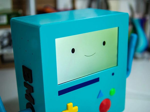
Who WOULDN'T want their own life sized BMO who could say nice things and help control their 3D printer??
I love using Octoprint to control my 3D printers, an open source plugin and web interface that gives incredible remote access to any 3D printer with a USB port. I also LOVE BMO from Adventure Time, the adorable little robot friend that accompanies Finn and Jake on their adventures and looks a bit like a giant Gameboy. Why not combine the two things to have a fun little robot friend who drives your 3D printer AND says nice things to you??
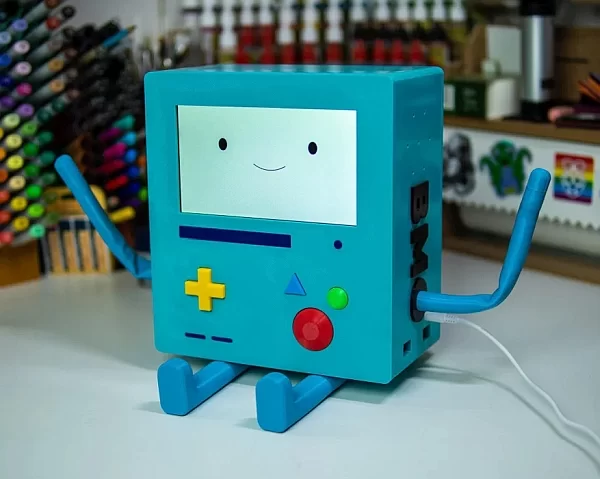
Introducing; BMOctoprint!
Be sure to watch the whole build video series on YouTube to get the whole experience of creating BMOctoprint and to help if you get stuck anywhere along the way. I've done my best to capture as much of the creation process as I can here, but BMOctoprint is a complex build, so please comment and ask if I've missed anything essential! You can also reach me on my website or on socialmedia!
(Since I have provided CAD files for BMO's case, it is possible to alter BMOctoprint to serve a different purpose or use different parts. However, I cannot accommodate for that and as such the instructions provided here follow along with how I have built and purposed BMOctoprint. Please feel free to create your own version if you feel so inclined!)
Supplies
This is a rather involved build with a fair bit of expenditure involved with a handful of parts being needed! Below are the components/necessary materials that I used to create BMOctoprint and therefore will work perfectly with the case/code as provided. If you wish to use different components then feel free, but alterations may be necessary to make everything fit!
Electronics (links are not affiliate links and UK specific)
- A Raspberry Pi 4 and SD card for the OS (I used a 8GB model which worked great and I recommend it. A smaller model may be fine as well or may run a bit slower.)
- (If you are going to be running Octoprint then a Pi 4 is a requirement as older models struggle to run it and I have not tested this setup with a Pi Zero.)
- 7 inch Raspberry Pi Touchscreen
- (This is super easy to use, fits the case perfectly and allows the Pi to mount right to the back of it. It is also quite expensive and there are probably cheaper options that can work with adjustments.)
- Adafruit I2S Speaker Bonnet
- One (1) extra long 40 pin header
- Two (2) 3 inch Speakers
- Three (3) 12mm Tactile Switches
- Four (4) 6mm Tactile Switches
- One (1) USB-C Panel Mount (capable of power delivery, this is important!!)
- Four (4) USB-A Panel Mounts (2 Left Angle and 2 Right Angle)
- Seven (7) 10K resistors
- A custom BMOctoprint PCB or other mounting for the tactile switches
Additional Components/Materials
- One (1) KG of Teal PETG filament (affiliate link)
- (Total printed weight will depend on your print settings, but 1KG should see you through)
- 50g Black PETG filament
- Small amounts of Yellow, Red, Green and Blue PLA
- 3mm Flexible Armature Wire
- Eight (8) M4x6 screws (cap head preferred for all screws)
- Four (4) M3x4 screws
- Eight (8) M3x8 screws
- Eight (8) M3x16 screws
- Two (2) 8x3mm Neodymium Magnets (optional)
I highly recommend a keyboard you can connect to the Pi as well to make setting things up easier, however, it is not required. You can do everything on the touchscreen, but it may take a lot longer than with a keyboard!
You will also require some basic electronics kit and tools such as a soldering iron, solder, a breadboard, kapton tape and a range of wiring. A 3D printer is essential as well, of course!
Pi Software Setup
To run all of the current code and software for BMOctoprint, you will need to use the Buster OS build of Raspbian.
The current build (Bullseye) will not work as OMXPlayer is not compatible with it.
I recommend downloading and using the Raspberry Pi Installer tool to get this set up.
Required Installs
- OMXPlayer (Documentation)
- OMXPlayer-Wrapper (Documentation)
- Xscreensaver (Documentation)
- Feh (Documentation)
- Octoprint (NOT Octopi!) (Install Instructions)
You don't need to install all of these things on your Pi just yet! I will come back to these things, but wanted to provided a list up front.
All print files, code and animations can be found and downloaded from my Github!
Step 1: Preparing Your Raspberry Pi & Display
(The next several steps are covered in the first part of the video series! Consider giving it a watch to see what's coming up.)
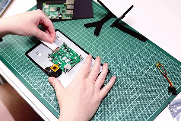
Getting your Pi set up with the touchscreen is going to be the first step, since this makes all subsequent steps a lot easier by providing both a mount for the Pi itself and a screen to control the Pi from!
Pimoroni have provided a detailed guide on setting up the screen itself, which is quite simple and straight forward! Screw the Pi onto the mountings on the back of the screen to secure it in a nice home. I recommend 3D printing the stand pieces from this Printables model to make it easy to see the screen while working!
Prepare your SD card with the latest stable build of the Buster OS from Raspberry Pi's website. I highly recommend using their Installer software as this will allow you to set up the install with your Wi-Fi credentials and password up front.
I must stress how important it is that you use the Buster OS and not Bullseye! You WILL run into problems later if you install the Bullseye OS.
Once you've got your SD card with the OS loaded, put it into the Pi and boot it up for the first time to get the OS installed and your Pi up and running! Test your touch screen to make sure it is working as intended.
Step 2: Setting Up for Sound
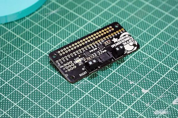
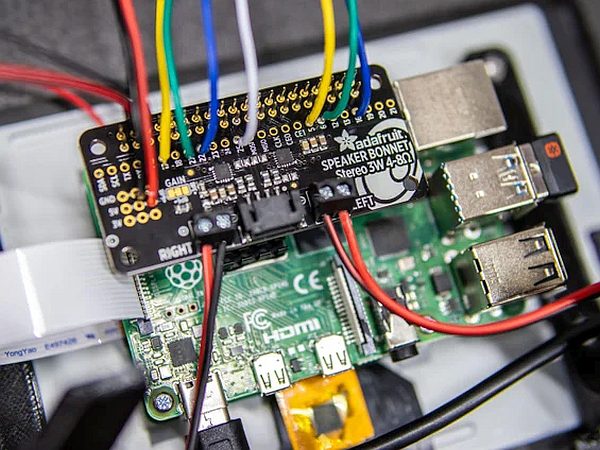
Next is getting the Pi set up for playing sound, which requires the Adafruit Speaker Bonnet. Adafruit have helpfully provided a whole guide on getting set up with the Stereo Bonnet, but I will run through a few key things here as well.
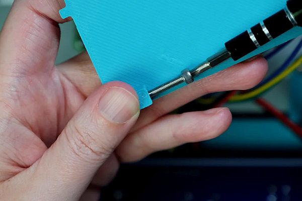
Most kits come with the speaker terminals not already attached, and since we will be needing those, solder those onto the board as seen above. I recommend using an extra long pin header to make sure there is plenty of pin length on the other side of the bonnet for attaching things to later.
Prepare your 3 inch 5W speakers by separating the wires a bit and screwing them into the terminals, making sure you match up the polarity with the indications on the speaker bonnet.
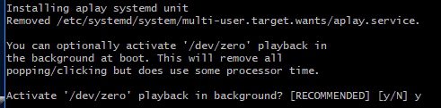
Install the speaker support scripts via the instructions on the Adafruit guide, but DO NOT activate the /dev/zero playback!
(Ignore what it says to do above.)
I found this made my speakers non-functional and caused other issues for me down the road.
Follow the Adafruit instructions to test your speakers to make sure your sound is working correctly!
(Ignore what it says to do above.)
I found this made my speakers non-functional and caused other issues for me down the road.
Follow the Adafruit instructions to test your speakers to make sure your sound is working correctly!
Step 3: BMO Button Testing and Custom PCB Setup
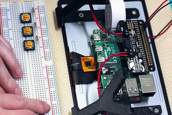
BMOctoprint's buttons are crucial part of his functionality, so getting those set up correctly is incredibly important! You'll need three (3) 12mm tactile switches and four (4) 6mm tactile switches to cover all of BMO's buttons.
To get started, set up your buttons on a breadboard with 10k resistors filtering the power through each button and connect each one to the Pi with a jumper lead. See the Fritzing drawing below to see how I set it up (ignore the sizes of the tactile switches inside Fritzing).
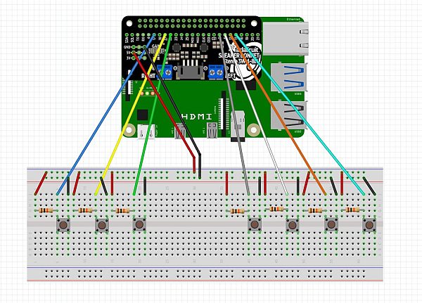
Make sure you set the right pin numbers if you don't use the same ones I did. Test all seven switches to make sure they are functional before moving on to soldering things!
Once all the buttons are tested working, you can move on to soldering the components to the final mounting. I have designed a custom PCB specifically for BMOctoprint, which can be purchased from PCBWay. You can also download the Gerber files from my Github if you prefer to fabricate your own PCBs. Alternatively you can simply use bits of permaboard or your own PCB! The mountings are made for the PCB which is 80mm x 175mm.
Regardless of what you choose, it's time to solder the tactile switches and resistors to the board, as well as soldering wires connecting the board to the speaker bonnet. I use kapton tape to hold everything in place while soldering! Make sure to measure out an appropriate length of wire so the buttons can sit in the right place in the case. You'll want about 6 inches/150mm of wire.
Once everything is connected, boot the Pi back up and run the test code again to make sure everything is functional.
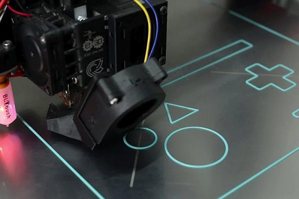
Step 4: 3D PRINT ALL THE THINGS
(If you want to learn more about how and why I designed BMOctoprint the way I did, as well as see it get built, check out Part 2 of the video series!)
Once you've got your electronics completed and ready to go, it's time to start making BMO's body! That means it's time for a LOT of 3D printing.
To get started, head on over to my Github to download all the required print files!
BMOctoprint's 3D printing files have been optimised to make printing as simple and straight forward as possible, however, as with all large 3D printing projects there is still a certain degree of prior 3D printing knowledge required to successfully create your build. I recommend that you be comfortable printing with PETG and have a good PETG printing profile for your printer, as there is a lot of PETG printing for this project.
These are large prints! Please proceed with appropriate caution or risk wasting filament!
In addition to all the individual pieces being available as STL files, there are also CAD files (.f3d and .STEP) that contain the whole model in ‘assembled' form. The large case parts have been optimised for use with either a 0.4mm or 0.6mm nozzle, while the smaller pieces print best with either 0.4mm or smaller nozzles (I have successfully printed the buttons with a 0.1mm nozzle, but that is hardly necessary!).
I highly recommend printing the large case pieces with a 0.6mm nozzle to save on print time. While a 0.4mm nozzle can be used, it will take substantially more time and will not save on filament.
Tolerances should be fine for most printers, but it is still recommended that you print the provided Test Fit pieces to check the fit of the pieces before committing to the larger prints. This will allow you to check the piece alignment/fit, as well as the fit for the screws. A M4x6 can be used to check the larger screw hole, and a M3x16 for the three aligned holes.
If you are struggling with tolerances and fit, it is possible to adjust these within the CAD files, but I'm afraid I cannot provide a range of part sizes for this due to the work involved. I am happy to advise on how to improve the fit but cannot provide additional files.
All STL files are in the best orientation for printing as is and don't require moving. Most pieces can be printed without supports, but minimal supports are required for some pieces. If unsure, print with supports!
Main case pieces and mounting pieces should be printed in PETG to handle the heat from the electronics without issue. I can highly recommend Polymaker PolyLite PETG (affiliate link) in Teal for this, as it is the perfect BMO colour!
BMO's limbs ideally should be printed in a soft TPU to allow for flexibility and posing! I used Recreus Filaflex 82A in Blue with great results, Polymaker PolyFlex 90A (affiliate link) works as well if you struggle with softer TPU. The Arm model comes in two variations; a whole version and a segmented version. If you are struggling to print the whole version in one go but don't want to use the segmented version (less clean looking) it's also possible to ‘slice' it into two pieces in your slicer of choice and use TPU welding to put the two pieces together. There are slots in the hands for neodymium magnets that can be pushed into place while the print is paused if you so desire.
Buttons and other detail pieces can be printed in PLA or whatever you please!
Some minor clean up may be required to get everything looking good and fitting together properly, but it should be minimal. If at all possible, print on a smooth or shiny print bed to get a BMO with a shiny surface!
Once you've printed the test prints and are feeling comfortable with the tolerances, get printing! It will be a good couple of days worth of printing to get everything done, so go do something else fun while BMOctoprint prints!
Step 5: Assembly: Part Clean Up and Prep
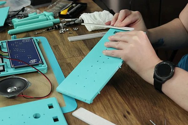
Once you've finished printing everything, you may wish to clean up some of the parts a bit. I've found sanding PETG to work quite well for rough bits, as well as using a tool like the 3D Simo to smooth things out. I found the areas beneath where some of the small face pieces glue on to be a bit rough, so I smoothed those out with my 3D Simo, but a soldering iron or other hot tool can be used as well.
Once that was done, I glued the small face details in place. Either plastic glue or super glue (CA glue) work well for this!
While your glue is drying, now is a great time to gather up your screws. To completely assemble BMOctoprint, you will require
- Eight (8) M4x6 screws (cap head preferred for all screws)
- Four (4) M3x4 screws
- Eight (8) M3x8 screws
- Eight (8) M3x16 screws
Step 6: Assembly: Preparing and Placing the Buttons
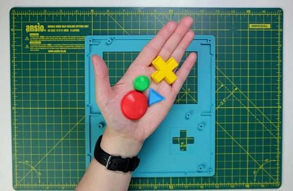
Gather up the buttons you printed, including all the little parts for the D-Pad.
Whilst developing BMOctoprint I tried MANY, many different styles of mechanism, for the D-Pad that could be entirely and easily 3D printed while still functioning to push four different tactile switches but not press ALL of them at the same time. This was no simple task! In the end I found this design to be the most effective, if not exactly perfect. (You can still push two buttons at once, but not all four.)
Your D-Pad push pads should press fit into the D-Pad without much effort. If they don't fit, re-print them slightly smaller until they do. If they are a bit loose, then add a dab of glue in the holes before pressing them in. The same applies to the centre pin.
Once assembled, place all four buttons in their respective slots. Make sure to orient the round buttons with the slot in back facing the same way as the triangle button. They should all look identical, as seen in the picture above. You should notice at this point that they don't really sit flat while the face place is resting on a flat surface. Grab a few evenly sized objects to set the face place upon so the buttons can sit flush. I used some test prints, but anything you have to hand will do, long as there is space underneath where the buttons sit!
Step 7: Assembly: Face Plate Mountings
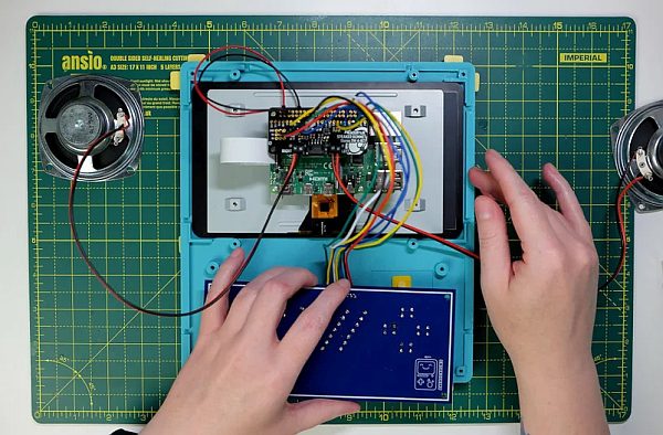 ‘Once your face plate is secure on your make-shift stand, it's time to place in the main electronics and screw them into place!
Gently set the touchscreen inside the space at the top of the print that is walled off at the corners. It should fit flush with a bit of wiggle room. Then align up your tactile switches with the holes in the backs of the buttons. Everything should fit nicely without needing too much coaxing.
Grab your display mounting pieces. There should be four in total, two each of two different lengths. In spite of the spec sheet for the Pi Touchscreen claiming that both sides of the screen are even, I found that they were ever so slightly different and as such required different lengths to mount with. If you find yours is perfectly even on both sides, simply use whichever mounting piece fits better!
Thread one M3x4 and one M3x8 onto each of the display mounts, with just enough of the screw sticking out the other side to latch onto the holes. Place the shorter mount pieces at the top of the screen and the longer ones at the bottom, with the shorter screws over the touchscreen itself. Screw firmly into place. Don't overtighten or risk breaking the print!
Use the other four M3x8 screws to secure the PCB onto its appropriate mounting points. Once in place, gently pick up the face plate to test your buttons press down on the tactile switches. They should be quite clicky so it should be obviously if the fit is good!
Step 8: Assembly: the Side Plates
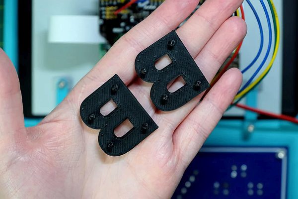
It's time to prepare the side plates for assembly! The Left and Right plates are similar but not identical; you should be able to identify which is which by the the registration marks that slot into the Face Plate. Set each one to either side of the face plate.
Grab your BMO letters as well and identify which go on which side. The print files are identified, but it's easy to forget which is which! As you can see above, the pegs are slightly different on each side! They should fit very snugly into the side plates, so be certain you have them aligned correctly before pushing them in. (They may be able to be pried out, but I've had mixed results with the pegs breaking off.)
Once the letters are pushed in, the speakers can be placed on their respective mounts and secured with the M4x6 screws.
The last components to be added to the side places are all of the panel mountings for the power and USB ports.
Please note that you MUST use panel mounts with 90 degree angled inserts or you will NOT be able to close the case up. The USB-C panel mount must also be rated for power delivery or you will get an Under-Voltage Warning.
It's also important to use a twist tie or zip tie to compress the cables for the mounts you attach to the right plate, otherwise the cabling will not fit between the speaker and the Pi. See the photo above to see how I have done this.
Lastly, attaching these panel mounts can be VERY fiddly, so I recommend pre-setting the screws in the panel mounts before attempting to attach them to the side plates. If the screw is struggling to register in the hole, you can use your screwdriver to enlarge the hole opening a bit.
Check everything is secure when finished and plug the other ends into the Pi itself.
Step 9: Assembly: Attaching Top & Bottom Plates (+ Arms & Leg Joints!)
Before we can attach the side plates to the face plate, we need to prepare the top and bottom plates. This can be done by pre-threading the M3x16 screws into the top sides of the bottom screw mounts on both the top and bottom plates (see photo). The registration marks on the top and bottom plates designate which side is up (registration marks are on the bottom, where it attaches to the face plate). Pre-thread the screws until they just prod out of the bottom of the mounting points.
Once that's done, set the top and bottom plates aside and gently pull one of the side plates into position using the registration marks on both the side and face plates. Be mindful of the wires and cabling while you do this! Make sure everything is siting in a nice place where it's not getting crushed or pulled.
Holding the side panel in place, take the top panel and place it gently into it's slot. The mounting point with the screw in it should sit on top of the matching mounting point on the side panel. These SHOULD line up perfectly if you did the test fit prints and printed the main body parts with the same profile. Once you've got that in place, it should hold on it's own enough to slide the other side panel into place as well; if not, tighten the screw of the side you've added just enough to attach the top plate to the side. Once both side panels are in place, secure all three sides by tightening the screws in the top plate the rest of the way.
Do not overtighten the screws, or you risk breaking the print. If this happens, remove the screws and glue the mount point back together, clamping the piece if possible. Wait until the glue is completely cured to continue.
Before attaching the bottom plate, grab the arms and arm plugs. Measure and cut a piece of armature wire the length of the arm (without having any protrude out the bottom) and insert it into the arm. This might take a bit of wiggling and coercion, but a tight fit is better than a loose one in this case! Attach the hand if necessary, and insert the arms into the arm holes and secure with the arm plugs. The plugs can be pushed onto the side panels to grip into place from the inside, making the whole arm unit secure in place.
If you put magnets in the hands, make sure the arms are facing the right direction to take advantage of this little add on! If you need to change the direction of the arms, pushing them inwards towards the body while pulling back the arm plug will release the hold.
After the arms are in place, you can attach the bottom plate the same way you did the top.
Just like with the arms, you want to cut a piece of armature wire for each leg as well, inserting that into place. Unlike with the arm, leave a bit of wire sticking out of the leg piece for it to attach more securely onto the leg joint, the small curved leg piece. As you can see, the leg plug also has a small hole to accommodate the wire, should you wish to put BMOctoprint in a (supported) standing position.
Push the leg joint pieces into the bottom, with the other side facing the table (BMO's front) and secure in place with the leg plugs much like you did with the arms. Leave the legs unattached for now.
Step 10: Assembly: Butt Flap & Back Plate
Before attaching the back plate and sealing BMOctoprint up (not permanently, of course!), the famous BMOctoprint Butt Flap must be assembled!
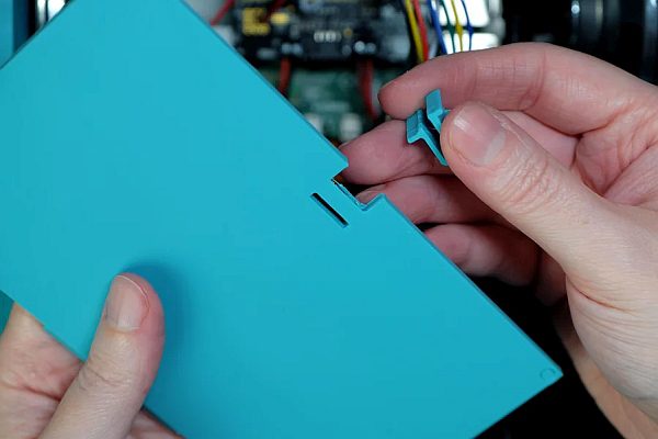
This is very easily done by slotting the Butt Latch piece into the opening at the top of the Butt Flap and gently squeezing into place with a pair of thin pliers. Use the small slot to gain purchase with the pliers to get the latch into place. If the opening for the latch is too big and it isn't staying in, use a small drop of glue to make the latch permanent, however, in most cases the latch should stay in place nicely on it's own.
Once in place, the whole Butt Flap can be attached to the back plate but putting the bottom notch into the small slot at the bottom of the back plate, and clicked into place. It should make a very satisfying sound! You can even test your Butt Flap by unlatching and re-latching it a couple of times. It's very fun.
Pre-thread the remaining four M3x16 screws into the backplate from the outside/shiny side. Once pre-threaded, place the whole back plate onto BMO's body, and make sure everything aligns properly. It should simply slot into place quite easily, but you might need to squeeze the sides a little bit. When everything feels lined up correctly, tighten all of the screws until they sit flush in the back plate.
Once secure, gently flip BMOctoprint onto her back, and attach the legs to the leg joints.
Congratulations! BMOctoprint is now fully assembled!
Step 11: Installing Octoprint & Enclosure Plugin
Please note that all further instructions require a basic knowledge and understanding of navigating the Raspberry Pi GUI and using a Linux interface. You will need to be able to use the terminal to install software, move files and set up code to run. A good resource for beginner info can be found here.
BMOctoprint wouldn't be BMOctoprint without Octoprint! Set your good robot kiddo within range of your 3D printer and plug it in with the official Raspberry Pi power plug. It should all boot up exactly how it did before you put the Pi inside the case and take you to the desktop.
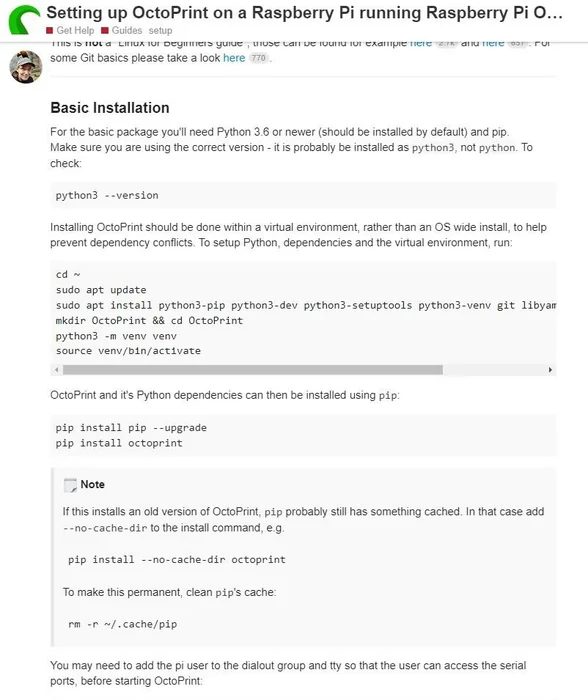
Under standard circumstances the easiest method of installing Octoprint (the OctoPi image) would be perfectly fine, but for our use case, it is best to install Octoprint direct to the Pi through a virtual environment. Gina Häußge created an amazing page walking you through the install process in a virtual environment onto a Pi so I recommend following that to get Octoprint up and running. If, like me, you ran into some issues getting the Octoprint server to autostart on boot up, I found this post to be extremely helpful to getting me over the hump!
Once Octoprint is installed and you've set up a the printing profile appropriate for your printer, you can plug your printer into one of BMOctoprint's USB ports to make sure it connects correctly. At this point, you can also direct yourself to the Plugins page in the Octoprint settings, and install the Enclosure Plugin.
On the Enclosure Plugin page, first set up a single Output to be a Gcode type. Call it Filament Change, Hide the UI Button, and put M600 in the Gcode text box. Save this and continue to the Inputs.
IMPORTANT NOTE: If your 3D printer doesn't work with the M600 Filament Change command, this will not work for you. I advise checking in advance that you are able to do filament changes this way before setting this up.
In the Input section of the settings, you'll want to create three different Inputs, naming each one after the appropriate button that it is for. Set the Input Type to GPIO Input, Action Type to Printer, and type in the corresponding IO number for that button. Leave the Pull Resistor as Pullup and the Event as Fall. Lastly, choose what you want each button to do! I chose Connect/Start/Cancel for the Big Red Button and Connect/Pause/Resume for the Little Green. For the Blue Triangle set the Action Type to Output instead, and select your Filament Change output.
Give your 3D printer a test run when you're done to see if the buttons work correctly!
Step 12: BMO Idle Animation Screensaver Setup
The next step is to get BMO to show us his beautiful little face every time she's left alone, so for that we'll need to get the screensaver set up to show a custom animation file.
Before going any farther, if you haven't already downloaded the animation video files and code files from the Github, now is the time to do so!
Place all of the animation videos and images in an easy to find folder on your Pi. You'll need to reference these multiple times in the next couple of steps.
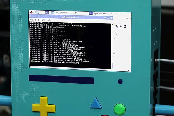
Open up the Terminal and install Xscreensaver:
sudo apt update
sudo apt install xscreensaver
Multiple additional packages will install alongside it, go ahead and say yes to the whole thing and let it install fully.
Once complete, open the settings from the terminal:
xscreensaver-demo
The screensaver preferences window will open, and on first opening you will be presented with a warning about the XScreenSaver daemon; go ahead and hit okay. From there you want to change the Mode to Blank Screen Only, and the time for Blank After should be set to 1 minute (unless you want longer, but this is what I recommend). On the Advanced Tab, enable Power Management and change the amounts to 30, 60 and 60. (This allows the Pi to turn off the screen after a little while so the idle animation isn't looping endlessly for hours consuming power.) Make sure Fade to Black While Blanking is ticked as well.
Once this is complete, check that OMXPlayer is installed (it should be by default, but it's good to check):
sudo apt install omxplayer
Open up the screensaver.sh file in your text editor of choice and change out the video path to direct to where you have the Idle Loop Animation on your computer. Save and close the file, and open up the Properties and make sure the Execute Permissions are set to Anyone.
Open the File Manager and make sure that ‘Show Hidden' is enabled, so you can get to the .config/autostart folder within the User Folder. If there is no Autostart folder, create one now. Place the screensaver.desktop file within the Autostart folder, opening it up inside a text editor and updating the path to point to where you have screensaver.sh saved. Once more save the file and make sure the Execute Permissions are set to Anyone.
Reboot the Pi and wait one minute after everything boots up. You should be greeted with BMO's lovely face!
Step 13: Setting Up BMO's D-Pad Animations
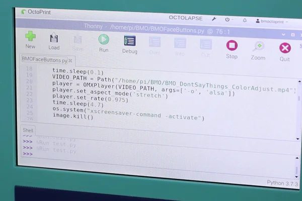
Getting BMO chatting up a storm is a rather easy step, since the code is already written and provided! Open up the BMOFaceButtons.py file in Thonny or your Python editor of choice, and redirect the video paths to wherever you have them stored on the Pi. From there, simply save the file and check the Execute permissions.
To ensure everything works as intended, open the Terminal and install Feh and OMXPlayer-Wrapper:
sudo apt update
sudo apt install feh
sudo pip3 install omxplayer-wrapper
Make sure everything installs fully.
To get the buttons to work on boot, copy the bmoanimations.desktop to /etc/xdg/autostart and open it in a text editor to redirect the path to where you have BMOFaceButtons.py saved. Save, check the Execute permissions, and reboot!
Once restarted, you should be able to trigger the four unique animations by pressing the D-Pad buttons!
If you find you are getting a black screen gap between the animations and the screensaver, you can try and eliminate this by altering the time of the
time.sleep()
command inside each video def. Decrease the number by small increments until the black screen goes away.
Adjust the volume as needed to get good sound for BMO's voice lines. I found mine best at 100% since the speakers aren't that loud, but your mileage may vary.
Step 14: Chromium Kiosk Mode
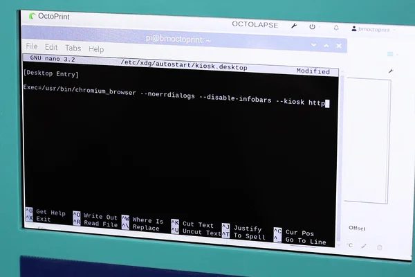
The last step is an easy one! I've provided the startup entry kiosk.desktop which needs to be placed in the same folder location as the animation startup entry, /etc/xdg/autostart. As with previous entries, make sure to check the Execute Permissions, as well as redirect the Octoprint web address to whatever yours is. Make sure to leave the & at the end of the line, it's important!
Before rebooting, open Chromium and check the Settings to make sure that it is always opening a fresh window on launch and not continuing the previous session! The alternate option will result in having multiple secret tabs open and eating up a ton of resources.
Reboot the Pi and watch BMOctoprint launch seamlessly into Octoprint on boot!
Step 15: Troubleshooting & Final Thoughts
Hopefully at this point you have a beautiful little robot friend who tells you nice things and allows you control your 3D prints directly on their face or from any browser! Unfortunately I am very familiar with the fact that there are MANY ways in which things can go astray during this build, so if you haven't had success, please don't fret! Re-check the instructions here to make sure you didn't miss anything as I have included MANY important notes and tips along the way to try and prevent issues. I have of course done my best to include every detail I could think of to improve the build experience, but I am alas human and prone to forgetting things!
If you DO get stuck somewhere along the way, please comment or send me a message and I will do my best to get you back on your way again, and will endeavour to keep these instructions updated as things crop up to try and prevent them from blocking others. Making is a collaborative endeavour, after all!
If you've made it this far, you're amazing!! Thank you so much for joining me on this journey and I hope your BMOctoprint is everything you dreamed it would be, just as mine has been! Please share your results here or with me on socialmedia, as I'd love to see your version!
Make sure to give me a follow here on Instructables and on YouTube to keep up with my making adventures and see what I come up with next!
Source: Life Sized Talking BMO From Adventure Time (that's Also an Octoprint Server!)