| Hardware components: | ||||||
 |
|
× | 1 | |||
|
× | 1 | ||||
|
× | 1 | ||||
|
× | 1 | ||||
| Software apps and online services: | ||||||
 |
|
|||||
 |
|
|||||
STORY
In my previous tutorial “ Creating a Raspberry Pi Universal remote with LIRC“, I show you how to set up a program called LIRC (LINUX Infrared Remote Control) so you can turn your Raspberry Pi into a universal remote. One common complaint about LIRC is its user interface, even setting it up can be a daunting process for someone that is unfamiliar with Linux. That is why I decided to use LabVIEW to create a graphical interface for LIRC. My LabVIEW VI's make it easy to set up and edit remote profiles. Sending remote signals is also much easier as well, you can now pick from your available remotes and remote buttons and send the command from your computer or tablet. In this post, I will walk you through my LIRC VI's.
Step 1: Setup
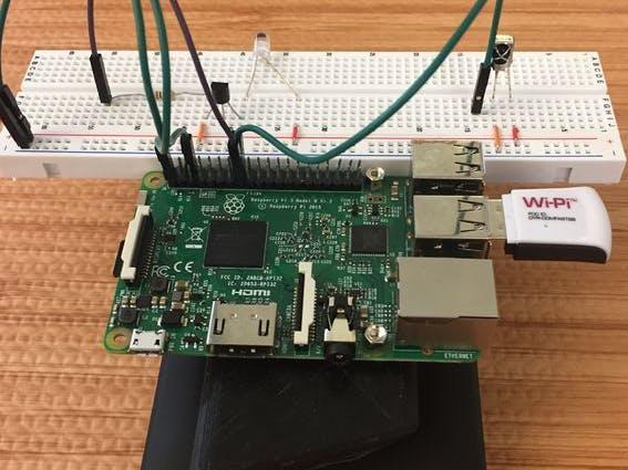
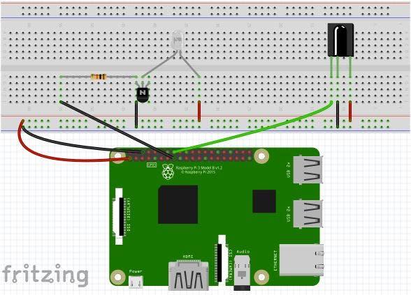
Although you can connect an IR LED directly to GPIO pins on the Raspberry Pi, the LED's output signal will be too weak, and the IR transmitter will have a very limited range. A simple transistor circuit solves the problem by amplifying the current output from a pin and thus increasing the IR LED's signal strength.First place your IR LED on the breadboard and wire the long leg(Anode) to 3.3 volts(pin 1) and the long leg(Cathode) to the Emitter of your transistor. Next, run a wire from ground(pin 6) to the collector of your transistor and then use a 10K resistor to connect the base of your transistor to pin 22.
First place your IR LED on the breadboard and wire the long leg(Anode) to 3.3 volts(pin 1) and the long leg(Cathode) to the Emitter of your transistor. Next, run a wire from ground(pin 6) to the collector of your transistor and then use a 10K resistor to connect the base of your transistor to pin 22. Next, place your IR receiver on the breadboard. Run 3.3 Volts to its right leg and connect its center leg to ground. Finally connect pin 23 to the left leg of your IR receiver.
Step 2: Materials
Hardware
- Raspberry Pi 2
- 940nm IR LED 40deg – 40 degree viewing angle. Bright and tuned to 940nm wavelength.
- 38khz IR Receiver – Receives IR signals at remote control frequencies
- PN2222 Transistor – Transistor to help drive IR LED
- 10k Ohm resistor – Resistor that goes between RPI GPIO and the PN2222 transistor
Software
Read More: LIRC LabVIEW User Interface for the Raspberry PI


