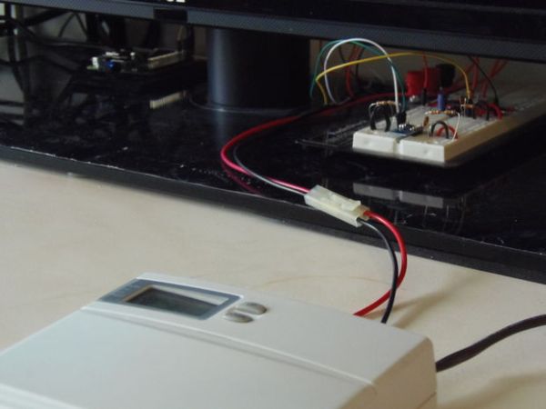
There are a lot of Instructables that show how to make a thermostat. But what if you already have a thermostat, and you want to log or monitor when it turns off and on? This Instructable shows how to use an optocoupler to obtain logic-level DC voltages from a common household programmable thermostat that connects to a 24 volt AC heating and cooling system. It also includes a temperature sensor, and code suitable for running on a Raspberry Pi to log and graph thermostat status, events, and temperatures.
WARNING: Working with electricity can be dangerous. Before continuing, be sure you have adequate understanding and skills to complete this project safely. While I've done my best to make it safe, I am not responsible if this project fries your thermostat, Raspberry Pi, HVAC system, your cat/dog, or burns down your house.
Step 1: Gather the necessary parts and tools
You will need the following parts:
- An HCPL3700 optocoupler
- 2x 3.3 kOhm resistors, rated 1/2 watt or higher (the wattage rating is important)
- A 10uF, minimum 10V capacitor (electrolytic is fine)
- A 0.1 uF ceramic capacitor
- An 8 kOhm resistor (or, more likely, a 4.7 kOhm and 3.3 kOhm resistor in series)
- A Raspberry Pi
- A length of two conductor, insulated wire, ideally with a quick disconnect of some kind
- Basic electronic odds and ends, such as:
- A breadboard
- Jumper wires
If you also want to build the optional temperature sensor, you will also need:
- An ADT7410 temperature sensor
- An SOIC breakout board
- Another 0.1 uF ceramic capacitor
- 4x 10 kOhm resistors
If you want to design and manufacture your own circuit board, you will also need:
- A two-terminal screw block
- Optionally, female header pins to accept the SOIC breakout board
- Male header pins to connect to a Pi, or female header pins to connect to an Arduino
- Optionally, SMD versions of the resistors listed above to cut down on overall size
Required tools:
- A multimeter
Other requirements:
- A 24 VAC heating/cooling system
Software requirements:
- Python
- Perl (needed for HiPi, which is needed for hipi-i2c)
- Plotly account (optional, for graphing data)
- Eagle (free version, optional, for designing PCB)
Step 2: Figure out how to interface with your thermostat
Many household heating/cooling systems run at 24 volts AC. (Those that don't are outside the scope of this Instructable). Programmable thermostats usually either run off of batteries, or use some kind of “power-stealing” mechanism to power themselves. The actual switching is usually done by a relay inside the thermostat.
We want to monitor whether the heating/cooling system is running. In order to do this, we want to sense whether the relay is allowing power to flow or not. The first step is figuring out which wires to monitor. Since thermostat wiring conventions vary, this requires some experimentation.
Grab your multimeter, set it to measure AC voltage, and figure out which pair of wires reads 24 volts AC when your heating/cooling system is active. Make sure this same pair reads 0 volts AC when the system is inactive. Note that you might have multiple pairs that will work, depending on whether you have a fan that automatically runs, or other variables.
My thermostat uses five wires, attached to six contacts (one of the wires is jumpered to two contacts). This means that there are 10 possible two wire combinations to test, and we should test these combinations when the system is both on and off. It's probably helpful to write out the pairs of wires you're testing on a sheet of paper, then note the voltage (or lack thereof) as you go.
You can see in my case, the actual voltage is higher than the nominal 24 volts. When the heating is on, my multimeter reads nearly 29 volts across the pair of wires I've selected.
Step 3: Give yourself access to the pair of wires
Turn off power to your heating/cooling system, and use your multimeter to verify that the power is off. Remove the thermostat from its base, exposing the wiring. Add two additional wires connecting to the terminals of the pair of wires you chose in the previous step.
To make things tidy, it's nice to use wiring that terminates in some kind of quick-disconnect on the other end, so that the thermostat can be quickly and safely disconnected from the project when desired.
Step 4: Wire up a circuit to measure the voltage
This is perhaps the most complicated part of the process. Obviously we can't directly connect 24 volts AC to a Raspberry Pi – something needs to rectify and step down that voltage and do so safely.
We can use an optocoupler to accomplish this. An optocoupler electrically isolates two separate circuits. In our case, we want to isolate the 24 volt AC heating/cooling system from our Raspberry Pi.
I chose to use the HCPL3700 optocoupler because it includes a rectifier and can handle a wide range of voltages. Specifically, it takes either AC or DC as input, anywhere from 5V to 240V, and can run off of a supply ranging from 2V to 18V. The current requirements are small enough to run the device directly from the Raspberry Pi's 3.3V supply.
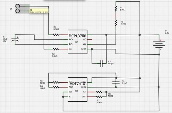
The included schematic shows how I wired up the HCPL3700 (you can ignore the bottom half of the schematic, which is the temperature sensor, for now). IMPORTANT: the two 3300 Ohm resistors connected to the AC input pins must be rated at least 1/2 watt. These two resistors set the trigger thresholds of the optocoupler, i.e., the input voltage at which it will turn on. For details about selecting these resistor values, see this application note.
The rectifier in the HCPL3700 rectifies the AC input, but does not smooth out the rectified sine wave. Thus, without any further input filtering, the logic output will rapidly oscillate, probably at the frequency of your line voltage (60 Hz in the U.S.). In order to avoid this, we place a capacitor across the DC pins of the rectifier. The application note has the details of how to calculate the value of this capacitor; a 10 uF, minimum 10V capacitor suffices.
Like many ICs, the HCPL3700 suggests placing a 0.1 uF capacitor across its supply voltage pins. Finally, the chip employs an open-collector output, which means it only drives its output low; in order to see logic-high outputs, we need a pull-up resistor. Calculating the appropriate value for this resistor is a bit of a challenge, since it depends on the characteristics of both the chip and the Pi's input pins, but I found that the standard 10k Ohm pull-up resistor could potentially not produce a high enough voltage to be read as a logic-high by the Pi. Thus, I went with an 8k Ohm resistor (actually a 3.3k Ohm and 4.7k Ohm in series). This calculation is based on worst-case scenarios, however; in practice, a 10k resistor might work fine.
For more detail: Log and Graph 24V Thermostat Events (Optocoupler + Raspberry Pi)


