
Introduction
The Lumenati line of LED boards is designed to give your projects an edge in their lighting capacity. Based on the APA102C addressable LED, these LEDs employ a 2-wire communication protocol consisting of a clock line and a data line. While this requires one more wire than standard WS2812B addressable LEDs, the advantage is that the communication with the LEDs becomes somewhat timing independent, allowing you to run these directly off of a Raspberry Pi or other single-board computer that doesn’t normally allow for a long, precicely-timed data stream without the use of additional hardware.
Required Materials
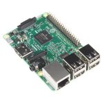
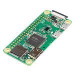
To get started, you’re going to need a control system. Either a Raspberry Pi or Arduino will suffice for our examples, but really anything that has GPIO can be made to work.
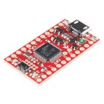
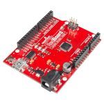
The APA102C addressable LEDs on the Lumenati boards operate natively with 5V logic, so it will save you trouble to choose a controller that can give you 0-5V, but it can be made to work with 3.3V logic with the use of a level translator.
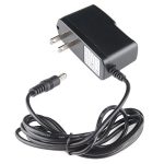
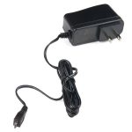
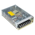
You will also need a power 5V power supply to run your controller and new lights. Each APA102C can draw as much as 60mA when red, green and blue are all full-on, so you’ll want to have something a little beefy. We’ve chosen a wall adapter capable of 2.5A, which should be plenty for our demonstration. But if you’ve got a bigger project in mind, check out the Mean Well 5V/20A supply.
Tools
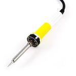
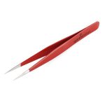
Lastly, you are going to need a few tools. A soldering iron, some solder, wire and a wire stripper should do. Maybe also some tweezers if you’re not comfy with having your fingers close to the tip of a soldering iron.


Hardware Overview
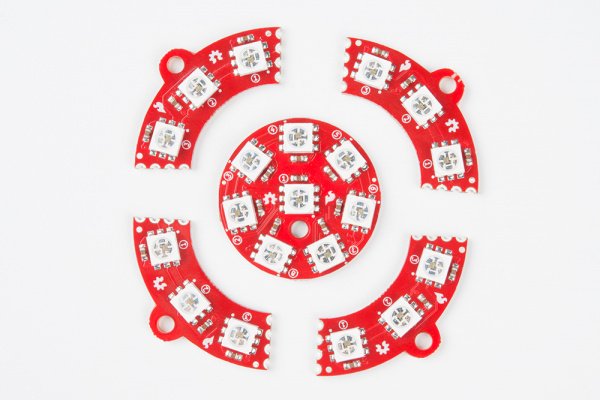
There are six different variations of Lumenati boards.
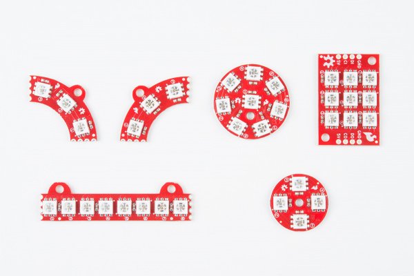
The various shapes of Lumenati boards.
Each of the Lumenati boards are shown below:
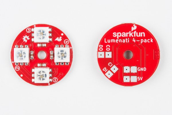
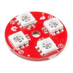
The 4-pack.
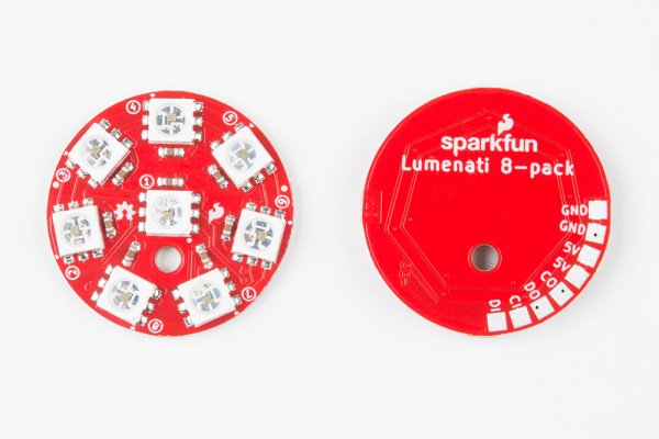
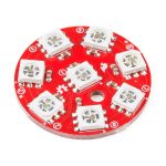
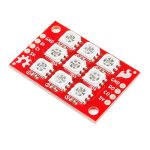
The 8-pack.
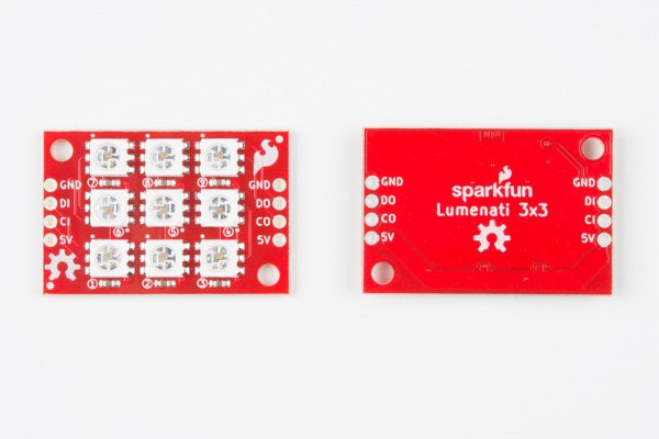
The 3×3.
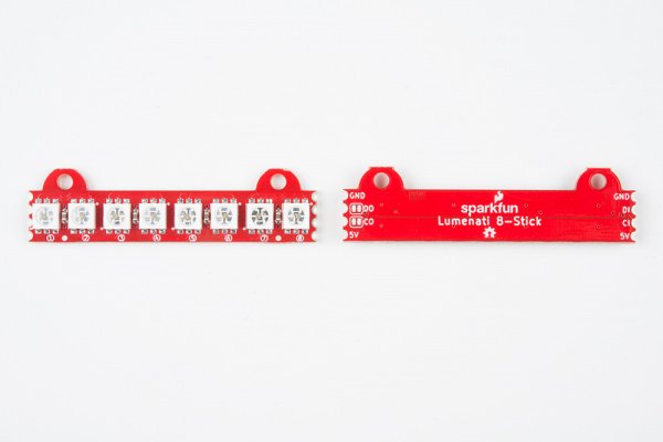
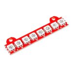
The 8-stick
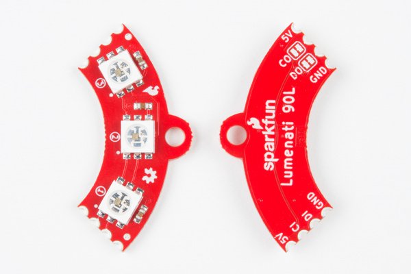
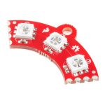
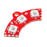
The 90L.
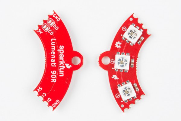
The 90R.
Daisy-chaining Lumentai Boards
Any of the boards can be used stand-alone or daisy-chained. However, the 8-stick, 90L and 90R were designed with easy daisy-chaining specifically in mind.
Castelated edge connectors. Just butt them up against each other and solder together.
There are also solder jumpers on the CO and DO (clock out and data out) of these 3 boards. Those are there so that you can interrupt those signals in case you make a closed-loop design where you don’t want the clock and data from your last LED to interfere with the clock and data to your first. +5V and ground traces are left to be contiguous in such cases to maximize current throughput. The solder jumpers on CO and DO come closed with a small trace bridging the solder pads. If you wish to open them, just take a small hobby knife (or similar implement of destruction) and carefully cut out that trace.
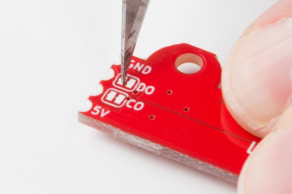
Make sure you cut the traces on CO and DO before powering up a continuous-loop design.
The APA102C addressable LEDs that are used on the Lumenati boards operate on +5V power input, as well as 0-5V logic levels for clock and data. The data interface is basically an SPI-like, with the exception that there is no data available coming back from the LEDs (no MISO line). Trace widths for +5V and ground have been maximized for better current through-put for long led chains.
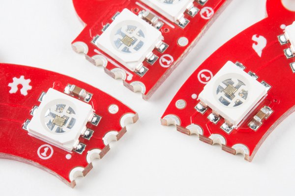
Additionally, LEDs on each board are labeled with numbers indicating their position in the sequence to help you design code more easily.

Check those numbers!!
As mentioned earlier, each APA102C is capable of drawing close to 60mA when it’s fully on. Care should be taken to keep that in mind when designing long LED chains. Figure out what your worst-case current draw could be, and plan accordingly!
Multiple Board Assembly
This section will cover the steps necessary to connect multiple Lumenati boards together.
Plan the Layout
For our demonstration, we’ll use four Lumenati 90L boards combined with a Lumenati 8-pack for a chain of 20 LEDs. Then we’ll drive them with a Raspberry Pi 3 in our first example and a SAMD21 Breakout in the second.
To begin, gather the boards you want to use.
You may want to sand or file down some of the edges left from the panelization of the PCBs to aid in fitment at this point, but we’ll leave that up to your judgement.
Soldering!
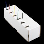
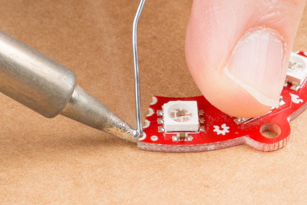
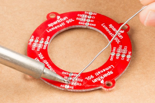
The four 90L boards will form a contiguous ring of LEDs. It would be difficult to get the clock and data signals off of the last 90L board (not impossible, but difficult), so we’re going to put the 8-pack at the beginning of the chain. First, we’ll solder up the four 90L’s. To do this, you’ll need a flat surface, preferably one that doesn’t burn too much. A piece of cardboard works really great for this! Tin one of the corner connections (either power or ground) on one of the boards with some solder, like so:
Then, butt the board you’ve just tinned up against the next board you want in the sequence, and reheat that solder you just placed so that it bridges between the two boards and forms enough of a mechanical connection to hold them together. Take care to make sure that both boards are as flat as you can get them to maximize both electrical and mechanical connections.
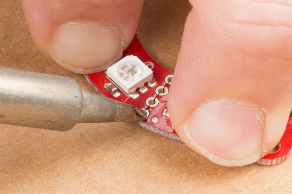
After you secure the first connection, solder the other three on both the top and bottom. This will make the boards as strong as possible. However, be aware that these can still break apart if put under too much stress. Mounting the boards to a solid backing is recommended, but they should still hold together fairly well if you’re making something like a Christmas ornament or the like. For our demonstration, we’re going to leave all the boards unmounted.
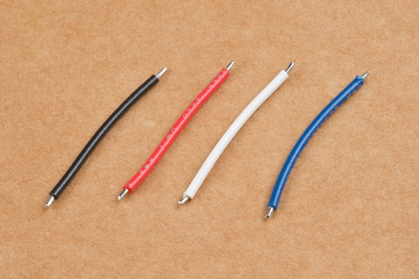
Next, solder the leads between the 8-pack and the four 90L boards. Cut four lengths of wire about 1 inch in length. We suggest color coding your wires for power (red), ground (black), clock and data (your call on those). Strip both ends of each wire about 1/16 inch to 1/8 inch, and tin them.
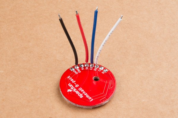
Tin all the solder pads of the 8-pack and solder your four leads to 5V (either of the two 5V pads), ground (either of the ground pads), CO and DO (Clock Out and Data Out). You can lay them out to the side if you wish, but we’re going to sit them straight up so as to make positioning of the PCB easier.
Place the 8-pack board in the middle of the circle of 90L boards you’ve already made. Figure out how you’d like the board oriented, and pick one of the four interfaces between the four 90L boards to which you’ll solder your four leads.
Once you’ve done that, solder down your leads – 5V to 5V, GND to GND, CO on the 8-pack to CI on the circle, and DO on the 8-pack to DI on the circle.
An alternate method of wiring to the 90L circle would be to solder up three of the four board interfaces leaving the fourth as open holes into which you can insert your 5V, GND, CO and DO lines. You will have to determine what your positioning is going to be before doing so.
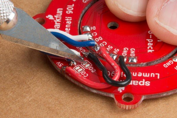
Now, you need to get power and signal to the thing you've constructed. To do so, just solder four more leads to the remaining 5V and GND pads on the 8-pack board, as well as CI and DI on the 8-pack. Braid the wires for some extra geek-cred. Now, it's ready to hook up to your control system!

Source:Lumenati Hookup Guide