
Breadboard
If you’re new to electronics and the Raspberry Pi (RPi), you might not be familiar with the breadboard. The idea of the breadboard is to allow you to connect up electrical components without needing to solder wires or any other elaborate procedure. It’s basically a grid with many holes, into which you can plug jumper wires, and build circuits. A must requirement for anybody recently getting a RPi, and wanting to try out different projects!
 The important thing to understand about the breadboard is how all the holes all connect up. First orient the breadboard with the short side horizontally, and the long side running vertically. In this orientation, the holes running in a horizontal line (the rows) are all connected to each other, with the exception of across the big indentation running down the centre. This gap allows you to connect items such as resistors across them, so that all the current is forced to pass through the resistors as opposed to through the breadboard as well. Looking down vertically, none of the boxes are connected, hence each row is it’s own independent line. On each side of the breadboard, there are two sets of columns with the ‘+’ and ‘-‘ symbols above them. These power rails are used to provide a power source (voltage) to the circuit. We won’t need these when using with a RPi, as the RPi will provide the power across the jumper wires.
The GPIO header
Before we start, its imperative you understand how the GPIO (general purpose input/output) header works on the RPi, as its vital to not only to know how to follow the tutorial, but also to make sure you don’t fry your RPi by using the wrong pins! The GPIO header is basically a set of pins, of which some are capable of sending and receiving current (the actual GPIO pins themselves), and the other’s serve a variety of purposes such as providing a ground (GND) wire. The actual GPIO pins are labelled simply with numbers (not on the RPi itself!), and are able to input or output a voltage of up to 3.3 V! This number is important, as some sensors may output more than 3.3 V, whilst other electrical components may not be able to handle a voltage up to 3.3 V. For this reason, it is extremely important that you use resistors where necessary to prevent exceeding this voltage barrier, especially when its being sent to the RPi! Some people recommend using a Pibrella breakout board, which basically connects on top of your GPIO header and ensures the voltage never exceeds this value. For our case today, particularly if you’re using the Monk Maker’s Starter Kit, we won’t need any resistors or have to worry about the voltage issue, as our components can work at up to 3.3 V.
Probably the most important thing to understand is how to read the GPIO header on your RPi, as the diagrams online don’t typically help you much with the orientation. Generally speaking, the first pin on the right side of the GPIO header (the 5V pin as seen on the RPi foundation website) is the pin which is near the corner of the RPi, facing the edge.
Final note, I’ll try to write this so its applicable to any electronics starter kit that you may have, but of course, different kits may vary and so things might be slightly different for you.
 Project information:
 Project information:
Estimated project time: 10 minutes
- Raspberry Pi
- A buzzer
- A switch
- 3 male-to-female jumper wires, and 1 male-to-male jumper wire
- A breadboard
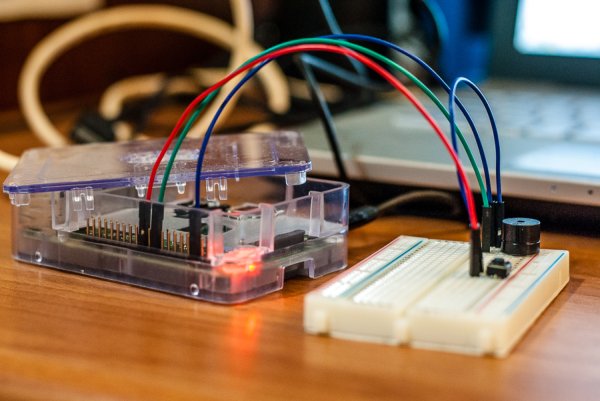
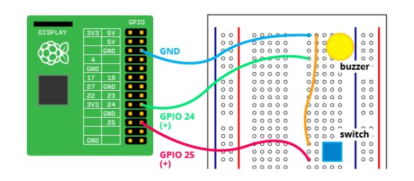
Plug in the buzzer into the breadboard, taking note of which leg is the positive lead. In the case of the Monk Maker’s Starter Kit, it is denoted by a’+’ sign on the top. In the same row as the positive lead, connect a green jumper wire to GPIO pin #24 (you may connect to any of the GPIO pins that can input or output a voltage, just make sure you write down which so you know which number to include in your code). Next, connect a blue jumper wire one in the same row as the negative leg. This will connect to the GND (ground) pin of the RPi which is at 0 V. This will ensure a 3.3 V potential difference (voltage) can be set up.
For more detail: Make an alarm clock with a Raspberry Pi