
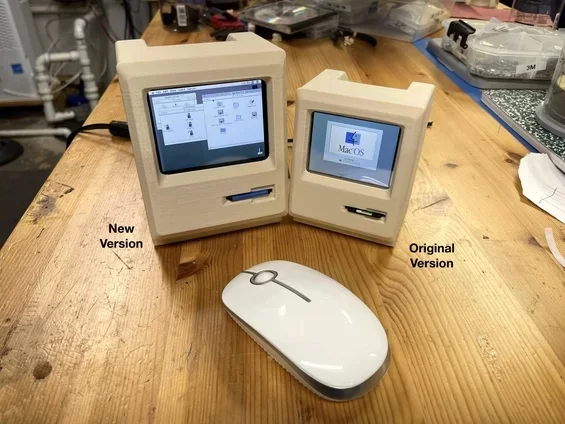
In this Instructable we are making a slightly larger version of the Tiny Mac. There are a couple of reasons you might want to make this version.
- Supply chain issues (it is almost impossible get a Raspberry Pi Zero)
- A larger screen
This version uses a 3.5 inch display. This version's is about 25% bigger than the Tiny Mac and about 40% of the size of original Mac. I've also included a version of the case of the Pi Zero if you have one. Look at the Tiny Mac for Pi Zero-specific instructions. Follow these instructions for the screen drivers.
I will refer to the original Instructable for much of the process. This Instructable will only cover the significant differences.
Supplies
Let's assemble what we need.
For The Raspberry Pi:
- Raspberry Pi 3A's or Pi 3B's (the case won't accommodate the 4)
- A 40 Pin Header
- A Micro SC card at least 16GB
- A compatible power supply (one with an integrated On/Off switch is a nice to have)
- A keyboard. The keyboard is only really needed for setup… unless the applications you will be running need keyboard input. Not sure I'd write a novel on this ;-). You can borrow a keyboard from your desktop.
- A mouse, wireless is a nice to have.
If doing the Pi Zero version, you will also need a mini HDMI to HDMI adaptor (for setup) and A small unpowered micro USB hub
In addition:
- Waveshare 3.5inch LCD For Raspberry Pi, 640×480
- A SHORT GPIO 40 pin Male to Female ribbon cable. An 8″ (20cm) should fit. Anything much longer would be difficult to squeeze into the case.
- Bluetooth speaker (optional). There are plenty of cheap options out there.
For The Case
- 3 – M3 X 12mm Hex Socket Head Cap Screws. Here is a nice assortment.
- 3 – M3 Hex nuts
- Beige PLA Filament
- Blue Painter's Tape for Raspberry Pi 3 version of the case
Tools
- 2.5mm Ball Allen wrench. Here's a full set of both Metric and US wrenches.
- 220 grit sandpaper
Step 1: Let's Start With the Case
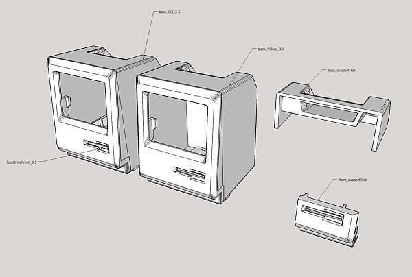
All the STLs should be oriented properly on the build plate.
I've attached the .stl files.
- All 4 versions of the front (front_3.5.stl (original Mac), front_SE_3.5.stl, front_SE30_3.5.stl and front_classic_3.5.stl) work with both the Raspberry Pi Zero version and the Pi 3 version of the build. Print with supports everywhere.
- back_Pi3_3.5.stl is obviously just for the Pi3. The Pi 3 version does not have an externally accessible SD card. Print with supports from the build plate only.
- faux_disk_Plus_Classic.stl is needed for the Pi 3, and used for the Zero version if don't add the SD card extension. No supports.
- faux_disk_SE.stl and faux_disk_SE30.stl are the versions needed for the Pi 3, and used for the Zero version if don't add the SD card extension. No supports.
- retainerClip_Pi3_3.5.stl secures the Pi 3 in place. No supports.
- back_PiZero_3.5.stl for the Zero only. Print with supports from the build plate only.
- driveFront_PiZero_3.5.stl for the Zero only if you do the SD card extension. No supports.
- driveBack_PiZero_3.5.stl for the Zero only if you do the SD card extension. No supports.
- toggle_PiZero_3.5.stl holds the Pi Zero in place. No supports.
The pieces should be oriented correctly for printing. The back_supportTest.stl and the front_supportTest.stl files are there if you want to experiment with supports before committing to printing the full parts. I've included the SketchUp file if you want to make changes. Check out the original Insturctable Step 2 for more details about printing and finishing.
Step 2: Preparing the Case
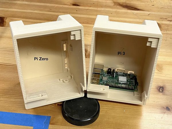
Take a look at the instructions in the original Instructable Step 3.
On the Pi 3 version of the case, you can use the retainer clip to hold the board in place. There are also places to use 4 – 2.5M X 10 cap screws and nuts. I'd recommend just using the retainer clip.
Step 3: The Faux Disk
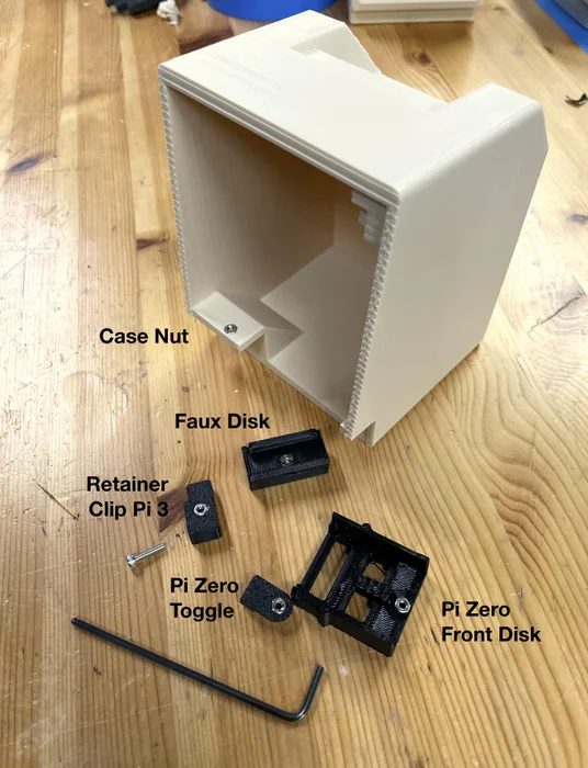
The faux drive is handled in a few different ways, depending on which front you choose. The Plus and the Classic use the faux_disk_Plus_Classic.stl with an inserted hex nut. The SE and SE30 fronts have a SD card support build-in. A different style faux disk is designed for each and will be held in place by back_PiZero_3.5.stl This step is for the Pi 3 version or if you don't want to relocate the SD card on the Pi Zero version.
Take a look at the instructions in the originalInstructable Step 4.
Using fauxDriveFront_3.5.stl, I placed the tape on a clean work surface and cut a strip 25mm (1″) wide. I then carefully wrapped the tape over the disk insert, centering it. Using a utility knife I cut off the excess.
Place the chosen Faux Disk onto the case and slide it forward so that the end with the disk protrudes from the front. Attach from below with one of the 3M cap screws.
Step 4: Follow the Original
For the next few steps, we will follow the original Instructable.
Step 6: Setting Up Your Raspberry Pi
Step 7: Collecting Your The Software
Step 8: Transferring Files To Your Pi Via CyberDuck
Step 9: Setting Up Mini VMac On Your Pi
Step 10: Optional System Upgrade
Take a look at the Waveshare documentation. There is an explication of just what the need changes are. We are going to simplify them a bit.
Needed files:
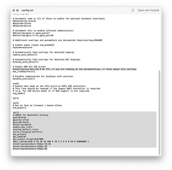
- the config.txt below
- a zip file from the Waveshare site. Decompress the zip file.
Take your Pi's SD card and insert it into your desktop computer. You have access to some of the files used on your Pi. At the root level you will find a file called config.txt. Make a copy of the file and rename it configOrg.txt. This is our backup in case something goes wrong. Drag your new config.txt file into the window. It will ask you if you want to replace the file. Go ahead. If you don't have rights, you and usually delete the file and add a new one. This file will tell the Pi to use the Waveshare screen as your default screen.
Looking at the root level, you will see a directory called overlays. Open that directory and drag in the 4 files from Waveshare's zip. waveshare-35dpi-4b.dtbo, waveshare-35dpi-3b.dtbo, waveshare-35dpi-3b-4b.dtbo and vc4-kms-DPI-35inch.dtbo
Eject your SD card and if building the Pi 3 version, insert it into your Tiny Mac. Otherwise hold on to it.
Step 6: Assembling the Tiny Mac
If you are using a Raspberry Pi Zero, follow Step 12: Assembling The Tiny Mac in the original instructable.
For those of you with the Pi 3, use the following steps.
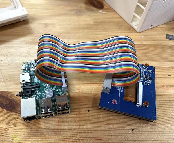
With the SD card installed in your Pi 3, carefully install the ribbon cable as in the photographs. The Female connector attaches to the Pi, the Male end to the display. Note the cable's orientation. Make sure it is aligned and fully inserted.
Carefully insert the Pi into the back of the case. Check the ports are aligned to the openings. Slide in the retainer clip and screw it in from below. (If you decide to use the 2.5M nuts and bots, install the card first and then the ribbon cable.)
Remove the protective cover from the screen. Place the screen between the tabs on the front cover. The cable will point UPWARDS. Move the cover closer to the back, allowing gravity to hold it in place. Becareful of the cables. Slide it upward under the tab in the top cover. With the Small Mac held together, insert a 3M X 12mm cap screw into the remaining hole on the left. Tighten into place.
Insert the screw from below and carefully tighten. You don't want to push the nut out of its pocket.
Step 7: From Here On, Follow the Original Instructable
Follow the original Instructable steps and you should be good to go with your slightly larger Tiny Mac!