
Introduction
Manufacturing companies have different ways to meet the market demand, some companies
deliver end products from their inventory to the customers. Other companies, instead of keeping
the finished goods inventories, they assemble or manufacture end products only after they
receive the customer order. However, producing finished goods to order does not necessarily
mean that the manufactured item is tailored to a specific customer’s requirements. For instance,
if the end products inventory costs are high, suppliers choose to manufacture only when the order
was placed.
Now a days, companies have more need to look towards customization more than ever, because
of customers unique set of demands in their orders. In order to satisfy customer needs,
companies have to supply products which address the wants of the consumers which made
companies to diversify their product portfolio. While diversifying the portfolio, companies are
making different products in order to address the customization problem at hand. Though
products are branded as different variants, versions etc. most of them are similar products with
little variations in their features or functions they perform.
While assembling these products, most companies use automated assembly lines but because of
the variations within the portfolio, the assembly lines has to be programmed repeatedly and
consumes a lot of time. Today, the development and validation of these controller software
variants require a lot of manual effort. This results in long market introduction cycles for each
new variant and therefore leads to some reluctance to bring new products to the market, leaving
business opportunities unused.
Therefore, in this research study, we proposed a simpler method to considerably shorten the time
needed for the development and evolution of new variants using techniques like feature based
modelling, materialization and pure::variants software.
Literature Review
As a result of rise in individualization of customer products in numerous industries during recent
times, much of the effort has been focused to increase the flexibility and versatility of assembly
lines by planning and developing decision models for the mixed model assembly lines [Boysen,
Fliedner & Scholl, 2009][1]. Shtub & Dar- El, 1989[2] developed a methodology to select a
assembly system by ranking possible alternatives in regards to subjective cost or benefit criteria
and, determined for assembly of low volume and high diversifiable products, high degree of
specialization of labor and its associated effects can be used to get most benefited.
Kull Hans, 2015[3], in his book Mass Customization Opportunities, Methods, and Challenges for
Manufacturers, describes mass customization as automated manufacturing of bespoke products.
Joneja, Ajay & Lee, 1998[4] describes mass customization as a trend that is being followed
undoubtedly by many industries. Tseng, 1996[5] proposed a product design methodology called
Design for mass customization for efficient manufacturing of product variants. In order to
achieve this, Tseng suggested to maximize the modularity in product design. Suh, 1990[6]
proposed a axiomatic approach and introduced product family structure as design basis to define
similar products.
Schmid & Santana, 2013[7] describes Product Line Engineering (PLE) as one of the few
industry ready techniques to manage reuse & variability, definably and hence bring software
development to further developed stage. The goal is to deliver exact product variants with quick
response times at a economical life-cycle cost with high quality. PLE is implement both in large
companies like Philips, Lucent, Boeing and Toshiba, and many small companies. PLE consists
of two life cycles namely Domain engineering which creates customizable software and provides
required assets to individual projects and application engineering uses the software provided as
basis for developing required product variant.
Automotive manufacturers are under pressure to deliver a wide range of product variants in order
to satisfy customers demands and managing these product variants has become a major concern
in automotive industry [Tarek & Hoda, 2010][8]. Flores, Krueger & Clements, 2013[9] defined
Second Generation PLE (2GPLE) to handle the product complexity, richness of variation in their
product family at General Motors. Using 2GPLE, GM has successfully managed their difficulty
to deal with complex and numerous product variants. Not only Automotive industry, many other
industries have been benefited by imparting PLE into their product lines specifically defense in
their satellite ground control systems[10], weapon test ranges[11], helicopter avionics
systems[12], submarine combat systems[13] etc.
Semi- Automated assembly lines are equipped with human operators and human factor proves to
be crucial in production systems due to their cognitive abilities, versatility and flexibility
demonstrated in facing unplanned events [Mura, Dini & Failli, 2016][14]. Many other factors
known as Performance Shaping Factors (PSFs) [15], can effect and cause errors in operator’s
performance, e.g., operator factors[16] such as worker’s memory, mental and physical abilities,
skills, training level, experience etc. Assembly line errors caused by human operators must be
decreased in order to reduce the cycle time which results in high productivity and efficiency.
In summary, there are many techniques to handle variability among the product variants and this
project discusses another reasonable method to handle and manage variability along with
techniques for aiding operators by better managing instruction manuals.
Background
Variability
Every company has to offer different types of products in order to satisfy wide range of
customer’s needs. Lately, customers’ demands are increasing and because of this, industries are
shifting towards customer-focused production allowing customers to specify product
components and features they offer. There are many problems associated with this transition
because production management systems are usually designed based on a limited number of
product variants [17]. Bachman & Clements, 2005[18] defines variability as a ability of a
system, an asset, or a development environment to aid the production of a group of artifacts that
vary from each other in a predetermined fashion.
In assembly lines, depending upon the complexity of the product, the number of parts needed to
be assembled increases which increases the complexity of assembly procedure. An automotive
system has huge number of components and allows customers to specify options such as motor
type, motor size, body color, interior and many add-ons. The number of different product
variants will be more in this type of scenarios and becomes very difficult to manage. The
traditional approach is to maintain a BOM (Bill of Materials) for each variant and this approach
will only work, if there are less number of product variants. A car in general has 20,000 to
30,000 parts [19] and this makes impossible to different product variants using traditional
approach.
Assembly Lines
Assembly line is one of the greatest invention in the 20th century. It was so beneficial and
efficient that the companies refuse to adapt this invention soon became extinct. Later Henry Ford
improved the assembly line concept and introduced the moving platforms of a conveyor system
in which the chassis of the car is moved from one station to another allowing the workers to
assemble the parts and finishing the assembly. GM installed its own robotic arm that could move
and assemble parts in a continuous pattern, repeated work is automated by the robots and the
operators are eliminated which resulted in better productivity and efficiency. Today robotics are
reaching a new level of advancement and companies are developing robots to adapt
manufacturing process and making them to work next humans. Along with robots, assembly
lines are equipped with Visual Aids, to assist the operators in complex assemblies to eliminate
unnecessary errors.
There are different types of assembly lines and they can be broadly classified into three
categories, namely:
● Manual assembly lines
● Automated assembly lines
● Semi-automated assembly lines
Manual assembly lines
An assembly line that consists of a sequence of workstations where the assembly tasks are
performed by human workers. Workers start with base parts and adds components along the line
to progressively build the product. Sometimes, workers uses portable powered tools to do
specific operations and production rate is relatively slow and error prone compared to automated
and semi-automated assembly lines.
Automated assembly lines
An automated assembly line consists of series of workstations performing predetermined
operations linked by a transfer system to move from one workstation to another controlled by
electrical control system. A fully automated assembly line doesn't require human operators
directly involved to make an assembly, every process is taken care by machines and automated
systems. In automated assembly lines, human operators are used for supervision, system design
and monitoring the process rather than operating.
Semi-automated assembly lines
In semi-automated assembly lines, both human workers and automated systems work together in
assembling the product. Human workers compliment automated systems by doing certain
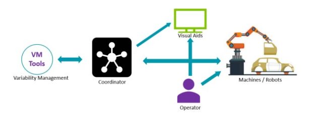
operations which are in capable of automated systems. The picture below shows the basic tool
chain of semi-automated assembly line.
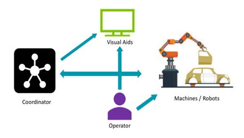
● Coordinator: Coordinator serves as brain of the Assembly line, instructs every other
member in the assembly line on what to do and when to do.
● Machines / Robots: These are the ones which does the maximum work and follows the
instructions of the Coordinator. Robots does not have idea of the process but follows the
instructions of Coordinator with in its capabilities.
● Operator: Robots are usually restricted by their capabilities and if a complex step occurs
in the assembly process which is out of Robots capabilities, then the operator performs
that specific task and enables the assembly process.
● Visual Aids: These can be as simple as pdf documents, Display unit or Virtual Reality
depending upon the complexity of the procedure and company’s budget. These are used
to aid the operator in the assembly process in various tasks.
Semi-automated assemblies are handling the assembly process efficiently without any fail and
provide high productivity rates according to the customer orders. But in some cases, companies
has to respond quickly to the varying customer demands especially when they are orders with
high variety and low volume. In this scenario, the coordinator has to be programmed specifically
for the order again due to the variety and requires a lot of manual effort. This results in long
market introduction cycles for each new variant and therefore leads to some reluctance to bring
new products to the market, leaving business opportunities unused.
Operator Instruction Manuals
Instructions for the workers in assembly line during assembly process plays a vital role and has a
significant impact on the production rates and had to be given high importance. Because of
numerous product variants, it is impossible for the operators to remember the instructions and
even maintain countless BOM and documents required for the assembly. Since, a better method
to manage these instruction manuals is required to aid the operators during assembly process for
better production rates.
Methodology
The objective of this project is to offer software product line methods, techniques and tools for
the development of mechatronic software controller variants considerably shorten the time for
the development and evolution time of new variants. This framework will strongly decrease the
manual efforts that are needed to implement controller software for existing product variants.
This will be achieved by selecting, linking and configuring the appropriate feature-related
components.
Software Product Line Engineering
Software Product Line Engineering (SPLE) focuses on developing software- intensive systems
using platforms and mass customization [20-21]. Software product lines (SPLs) are the most
successful methods to increase productivity, lower costs and shorten time-to-market in software
engineering businesses [22]. SPLs facilitate organizations to reuse of software by developing a
family of products that share some commonality, but differ in several aspects.
Domain Engineering
Domain Engineering [23] focuses on the development for reuse, where one develops artifacts for
reuse and these doesn’t result in a specific product. These artifacts can be used in developing
specific products.
● Domain analysis: Where we define all our features, variability and constraints which
define all family of products including scoping and variability modelling.
● Domain implementation: In this module, one develops all the domain specific source
code, tools, models which are used to produce or used for all family of products rather
than a specific product.
Application Engineering
This focuses on the developing specific product according to the needs of a particular customer.
This is connected to the Domain Engineering space and the specific product requirements are
derived from the artifacts developed for reuse.
● Requirement analysis: This module offers the customers with options for selecting
required features according to their needs and requirements.
● Product Derivation: Specific product according to the requirements of the customer is
derived including validation and verification of the constraints associated with
requirement analysis.
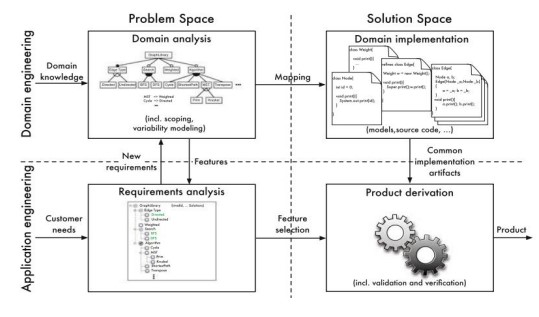
As an overview, Domain analysis and Requirement analysis can be constituted as Problem
Space, which focuses on perspective of the stakeholder’s problems, requirements and gives an
idea on the entire family of products with features and capabilities they offer. While Domain
implementation and Product Derivation can be constituted as Solution space, which focuses on
design, implementation, validation and verification of features and their combinations so that
systematic reuse is availed [23].
Variability Management
Variability management is a key activity in software product-line engineering [24]. There has
been a lot of studies going on since 1990s [25]. There are a lot of approaches have been
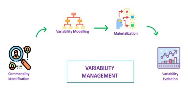
introduced to the industry from last two decades. Variability management involves specific
activities to handle and manage variability. Some of the key activities are Commonality
Identification, Variability Modelling, Materialization, and Variability Evolution.
Commonality Identification
SPLE exploits the commonalities of the products that belong to a product family and handles the
variation among the products. Commonality is a feature that is shared by all products of the
product line [26]. The main aim of this activity is to identify all the commonalities within
product family.
Variability Modelling
Variability is expressed by feature models, variability expressed in relation a base model
[27][28]. Commonality and variability of a product family can be modelled in many ways based
on different viewpoints [29]. In problem space, user goals, objectives, constraints are modelled
in product line engineering. There are two modelling techniques which are popular in the
industry. They are Feature Modelling and Decision Modelling. Feature Modelling is the one
which is extensively used in software product lines compared to Decision Modelling.
Feature Modelling
Feature Modelling was first introduced in the Feature-Oriented Domain Analysis (FODA) by
Kang et al. (1990), since then it has been widely used in software reuse methodologies along
with Software Product Line Engineering (SPLE) as means for modelling variability in product
line i.e., a family of products. Feature modelling is an analysis technique which is used to define
product line i.e. family of products [30]. Feature is defined as a distinctive quality or
characteristic of a software system or system. An example of a Feature Model is shown below:
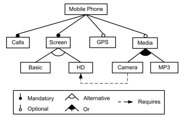
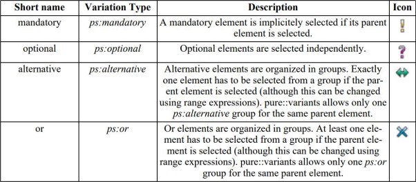
The relationship among features can be divided into [31]:
● Mandatory. If a feature is defined with a mandatory relationship with its parent feature,
it should be included in all the combinations in which its parent feature appears. In the
above Figure, all mobile phones should support calls.
● Optional. If a feature is defined with a optional relationship with its parent feature, it
may or may not be included in all the combinations including its parent feature. For
example, GPS is defined as an optional feature, so it may or may not be a feature of
mobile phones.
● Alternative. A set of child features are defined with alternative relationship with their
parent feature where only one of them can be selected when its parent feature is part of
the combination. In Figure, mobile phones might provide support for Basic or HD (High
Definition) screen, but not both of them at the same time.
Or. A set of child features are defined as an or-relationship with their parent when one or
more than one of them can be included in the combinations in which its parent feature is
included. In Figure, software for mobile phones can provide support for Camera, MP3 or
both in the same combination.
In addition to the hierarchical relationships between features, a feature model can also contain
constraints which makes the model robust and helps to define the model completely. These are
usually of the form:
● Requires. If a feature X requires a feature Y, if feature X is included in a combination
implies that feature Y should be included in such combination. In Figure 1, mobile
phones including the feature Camera must include support for a HD screen.
● Excludes. If a feature X excludes a feature Y, both features cannot appear in the same
combination.
Product Feature Model (PFM)
PFM describes the variability of family of products in terms of product features, which can be
classified into parts, capabilities, domain technologies, operating environments and
implementation techniques as defined in FORM [32]. The most common usage of feature
diagram is to represent a Product Feature Model [33].
Materialization / Product Derivation
Product derivation [34] in software product line engineering is the process of constructing a
product based on the user selection of features defined. Feature selection is determining the
optimal choices that satisfy product goals and quality requirements [33]. Based on the selection,
only selected features are derived and the information is carried out for production or next steps.
The product derivation is generally automated process depending the tools (Enterprise Architect,
Pure Variants etc.,) one uses.
Variability Evolution
Product lines are long-lived software systems supporting companies with changing customer
requirements [35]. Variability models evolve and grow together with the evolution and growth of
the product line itself [36]. Whenever a new feature is added to the product line or a new product
is added to the family of products, instead of recreating the feature model with new
arrangements, feature models are constructed to support evolution of variability. New features
are added to the existing feature model which significantly reduces the development time for
new variants.
The whole variability management process is automated and aids the cycle times of product lines
to be faster. Different software are used to help the variability management to be managed easily
and intuitively.
Tool Chain
Variability Management tools like Pure Variants, Magic Draw (for modelling), Lieber Lieber
Embedded Engineer (for code generation) are used to manage the variability and make the
assembly line capable of producing different products on a single assembly line.
Variability Management Tools
Pure Variants
The pure::variants [37] is a commercial variants and variability management suite. The main
goal of pure::variants if to provide a systematic way to express and define variability and variant
information throughout the life cycle of a product line. It is designed to complement the existing
development tools and provide the required links between the tools in order to aid efficient
development of variant-rich systems.
The pure::variants tools uses a uniform meta-model to define variability [38] in the problem
space (feature models) and solution space (family models) and a related meta-model to describe
variant combinations (variant description models). In a typical use case portfolio in
pure::variants, product managers define the planned and intended product commonalities,
features and variabilities in feature models. Out of the defined features in feature model, one
selects the required for a particular product and assign the features of products in variant models.
Different variant models for specific variant of a product and there can be as many as variant
model for a single feature model. Each variant model has a single product’s configuration.
Feature Models
Feature model are used to express commonalities and variabilities efficiently. A feature models
explains features and their relations. A feature is a property with respect to the commonalities or
variation between the products in the product family. The relations define the connections
between features whether they are optional, alternative or mandatory.
With respect to the features and relations, a feature model is constructed which defines product
family by expressing the commonalities and variability.
Variant Description Model (VDM)
Variant description model allows the users to select the intended features of the desired product
from the feature model.

The figure above shows both feature model (.xfm) and variant description model (.vdm) of a
product CAR. The feature model CAR.xfm has a product CAR with mandatory features Body,
Transmission, Engine and an optional feature Pulls_Trailer. Also Transmission has child
attributes Automatic and Manual as alternatives so that user has an option to select only one
option either Automatic or Manual. Mandatory feature Engine also has two child attributes
defined as an optional feature, Gasoline and Electric providing user with option to select either
one of them or both.
Transformation Modules
There are many transformation modules available in pure variants, which helps the variant
management system to be efficient and complete, can be found in [39]. With respect to this
project, there are two transformation modules which helped the tool chain to be complete and aid
the variant management process to be automated. They are:
● JavaScript Transformation Module
● Microsoft Transformation Module
JavaScript Transformation Module
The pure::variants offers JavaScript transformation module for generating a product variant.
There are no special requirements required to use the transformation module and one use it right
away. The main goal of the JavaScript transformation module is to access the features in the
feature model. If a user selects his desired features in the variant description model, this module
helps to map those selections and helps to create a product variant. Following are the instructions
to create a JavaScript transformation module:
● Open the transformation configuration page in the Configuration Space properties.
● Add the JavaScript Transformation module using the Add button. Name it for instance
Execute JavaScript.
● The module parameters can be changed on next page.
● Enter the path to the script file you want to execute as value of the JavaScript file
parameter.
● An (optional) output file can be specified using the output file parameter.
● Press Finish to finish setup of the JavaScript transformation
The script consists of three main functions. These three functions will be called by the
transformation module.
● init() This Method is optional. Necessary work can be done here, before transformation
starts, like initializing the script. Gets necessary information from transformation module,
like the used variant model, the used models in this variant, some variables and the
transformation parameters. All this information can also be retrieved from the JavaScript
transformation module using getter functions.
● work() Does the whole transformation work.
● done() This method is optional. After transformation is finished, this function is called, to
provide possibility to do some work after transformation.
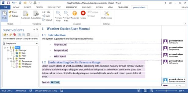
Microsoft Word Transformation Module
The pure::variants Connector for Microsoft Office enables the use of product line variability
concepts in Microsoft Office Word and Excel documents [40]. It allows to maintain one master
document from which different document variants are created automatically by selecting features
from Feature Models in pure::variants. So instead of having to merge changes in slight variations
of the base documents, the change is applied once to the master document and then all relevant
variants are automatically generated by pure::variants.
The pure::variants connector can be installed in the Microsoft Word as an plugin, which makes it
easy for the users to create a single master document and define the content according to the
feature model.
The figure above represents the pure::variants Ribbon Tab with user interface elements after
installing the pure::variants plug in Microsoft word application. The user interface elements
function are explained below:
● Show: Shows or hides the pure::variants task pane.
● Open: Opens a configuration space or other pure::variants models (.xfm, or .ccfm). See
the section called “Using the pure::variants Task pane” for details.
● Reload: Reloads all loaded pure::variants models and refreshes the visualization.
● Condition: Adds a condition to the current text selection.
● Calculation: Adds a calculation to the current text selection.
● Hide: Hides all variability information.
● Split: Splits the commented area of an existing condition or calculation at the current text
cursor location. The text cursor must be inside exactly one commented area.
● Extend: Extends a commented area of an existing condition or calculation with the
current selection. If the current selection overlaps with exactly one commented area, the
overlapped area is extended with the selection
● Preview Grey: Preview visualization, which grays out all elements that would not be
included in a variant produced with the currently loaded variant model
Preview Hide: Preview visualization, which hides all elements that would not be included
in a variant produced with the currently loaded variant model
● Warnings: Visualization that highlights all conditions and calculations that contain
semantic errors in the pvSCL expression, such as unknown names of features or attributes
● Errors: Visualization that highlights all conditions and calculations that contain syntactic
errors in the pvSCL expression
● Previous: Jump to previous faulty condition or calculation.
● Next: Jump to next faulty condition or calculation.
● Preferences: Opens the preferences dialog
Editing Variability
Users can create a master document like normal document in Microsoft Word application. The
plugin integration provides an editor, which features auto completion, syntax highlighting and
checking for errors. There are two ways one can define variability in this transformation module
either by conditions or calculations [41].
● Conditions: Conditions are the pvSCL expressions that return with a Boolean value,
either true or false, which decides whether the annotated text should be in the resulting
variant or not. To annotate the text and assign a condition, select the desired text and
click Condition button. An editor dialog box opens, enter the condition within the box
and it also has features like auto-completion and syntax highlighting.
● Calculations: Calculations are the pvSCL expressions that return a value, which replaces
the entered text during transformation.
Magic Draw
Magic Draw is the award-winning business process, architecture, software and system modeling
tool with teamwork support. Designed for Business Analysts, Software Analysts, Programmers,
QA Engineers, and Documentation Writers, this dynamic and versatile development tool
facilitates analysis and design of Object Oriented (OO) systems and databases. It provides the
industry's best code engineering mechanism (with full round-trip support for Java, C++, C#, CL
(MSIL) and CORBA IDL programming languages), as well as database schema modeling, DDL
generation and reverse engineering facilities[42].
The Unified Modelling Language (UML) is widely used in the development of software
development and also for its customizations, for computer based software, business process
modelling and system design [43]. Instead of using UML as a documentation tool, we tried to
use it for defining the system and generate code from it using Magic draw (defining model) and
Lieber Lieber Embedded Engineer (code generation). The following are the steps to create a
model with activity diagrams and state machine diagrams.
Creating a model according to the use requirements from scratch
To create a model from scratch according to the requirements, one has to do the mandatory steps
in order to lessen the hassle during code generation.
● Create a new project
● Create a new package in the project
● Now open up a existing and working project(Guessing_Game)
Copy the following folders under the package of Guessing_Game
EE_PrimitiveTypes_Package
Usings
EA Profile
Embedded Engineer
● Go to the Package and also copy the folder FSM and Class signals.
● Check all the inner elements of FSM and FSM_State and their data types. (Note :Having
correct data types for all the declarations helps us eliminate a bunch of errors during
Code Generation times)
● Now start with a class and build your own model.
● When defining the operations and Opaque Behaviors inside the class make sure that both
operation and Opaque behavior are connected to each other by directing them in
Specification(Opaque Behavior) or Method (Operation)
● It is advisable to create both Operations and Opaque behaviors by going into
specification of certain Class
Example for creating a new Operation
● Right Click on the class where you want to create and go to Specification
● On the left hand side there’ll be a containment tree, choose Operations
● In order to create a new operation, click on create on the lower right hand side
● Give all the required details and press OK
Similarly go to inner elements in order to create an Opaque behavior.
● If we create the Operations and Opaque Behavior in the containment tree itself
sometimes it might not create the code and give errors like, the function was not defined.
So it is advisable to create the Operations and Opaque Behaviors as described in Step
above.
Creating an Activity Diagram
To create an activity diagram [44] for certain activity user can go to diagrams in the menu bar
and create an activity diagram or Right Click on the class under which the activity is going to be
and go to diagrams and then activity diagram.