
Introduction
In this sample, we will connect an RGB Controllable LED to a Raspberry Pi 2 and vary the intensity level of each color using a technique called Pulse Width Modulation (PWM).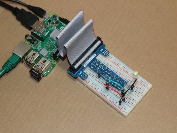
The ability to control the level of intensity of each of the three colors on the LED will allow us to make an infinite number of color possibilities. How can we control the intensity? An LED's intensity can be controlled in one of two ways. The first way is to control the amount of current going to the LED. This approach is somewhat complex and requires additional hardware. The second way is through Pulse Width Modulation and can be done with a few basic parts and the right code (for a good explanation of what PWM is an how it works see this blog: “PWM – What is it, How does it work and how to detect it“).
It is commonly known that the Raspberry Pi 2 only has only one pin for hardware based Pulse Width Modulation and therefore cannot be used to drive the three pins on the LED. To accommodate this, a software based PWM is needed. This sample will demonstrate how a software based PWM can control the intensity of the LED. The trade of between a hardware based PWM and a software based PWM is gong to be CPU overhead versus additional hardware. Although using a software based PWM has some limits it will get the job done!
Even though the GPIO APIs are only available on Windows IoT Core, this sample can run on your desktop but, of course, will not attach to the controller. This is because the sample uses the new meta data API's found in the Windows.Foundation.Metadata namespace to detect the presence of the GPIO Controller. This is useful to allow the code to be run on your desktop to help debug other aspects of the application.
Build the Circuit
Let's start by constructing the simple circuit. In this example I use a small breadboard with a cobbler board and 40-pin ribbon cable to connect the Raspberry Pi 2 GPIO to the board (using a cobbler and ribbon cable is not required). If you do not have these components I have included a wiring diagram that shows you how to connect directly to the Raspberry Pi 2 pins. Note that the hardware list calls for male to male connectors when using the cobbler board. If you choose not to use the cobbler board you will need the same number of wires, but male to female instead.
When placing the cobbler board on the breadboard, I have positioned it so that the first pins are in row 1 which positions the four pins for 5V+, 5V-, 3V3+ and 3V3- into the second row. The pin farthest from the ribbon cable on the cobbler is in row 20. Having this exact positioning is not critical but will help you follow the wiring diagram in this sample. The pins that are used by the cobbler board are highlighted in the diagram below.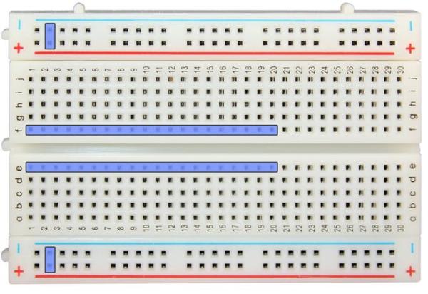 Start by placing the LED onto the breadboard. The red lead will go into position J26. The common cathode lead is inserted into J25. The green lead is inserted into J24 and the blue lead into J23. You will need to spread the leads out slightly to get them to insert at the same time into the these four positions on the breadboard.
For more detail: Many Colors with Variable RGB LED