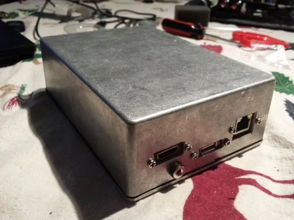
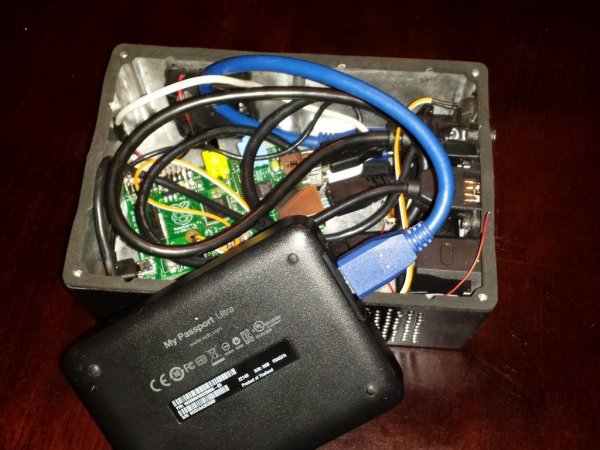
I travel a lot and I like to take my media with me. However, I'm rarely end up at places with a strong internet connection and I don't like having to hook up my laptop to the TV. So a couple months ago I decided to build a portable media computer, and as a result, Mjölnir was born.
Mjölnir (so named because it looked like Thor's hammer before I painted it), is essentially a Raspberry Pi, a powered USB hub, and a portable HDD tucked inside an electronic enclosure.
The Raspberry Pi is great, especially when it's tucked away behind a monitor. However, it isn't perfect as a something to carry around with in your travels. To make it as small as possible the connections are all on different sides of the board. Plus, once you've found them all, you have to hook up the pi to a hub, the the hub back to the pi to power it, and then your portable HDD into the hub, then plug in power to the hub, HDMI into the pi, and ethernet. . . . on and on. And a crow's nest of wires does not look very good.
Mjölnir was born out of a need for simplicity. I wanted it to be just like a tiny computer, all the ports at the back, just plug things in and go.
If you follow these instructions you too can have a portable media computer for around $215.
POST NOTES:
Wow, the feedback and response to this has been incredible. Thank you to everyone that has viewed it and commented. I'm glad the majority of you like it. After recieving some feedback I'll try to clarify some points I failed to make in my instructable:
- Orientation – The removeable plate is actually the bottom. I attached bits of Sugru to that for feet, and after I closed the lid I flipped it over and that's the bottom. Showing pictures of the internal configuration made it confusing, because when you see inside the case with the panel removed, you're actually looking at it upside down.
- WiFi – Originally i had one of the ports on the USB hub for a WiFi Dongle; however that thick aluminum blocks all WiFi. I don't need WiFi (like I said I use this mostly in places where there isn't internet); but if you' need one I'd recommend buying another USB panel connector and mounting it just above the first one. There should be an open port since I have my fan plugged into the Pi directly.
- Fan & Temp – Yes, that is a 12V fan, and yes USB only puts out 5V. It doesn't run at full speed (or even half speed), but it moves enough air for the little heat my HDD makes and it's super quiet. I watched many hours of full 1080p content over the weekend and the Pi's CPU never got above 54C.
- The OS – I'm running RaspBMC (http://www.raspbmc.com/) which is a custom Linux kernel based on Rasbian which in turn is based on Debian Wheezy. Once installed it boots directly into XBMC which is all you can use. This was a big plus for me, because this makes it very user friendly for my friends. If you're looking for a full fledged computer with a browser, games, etc. this probably isn't for you.
- The Pi will also support OpenElec (XBMC) and RasPlex (Plex) as OSes.
- Control – So one of the reasons I choose the Pi is because it supports CEC over HDMI. This means that MOST newer TV's can control the pi using their factory remote. This was a big plus for me, because this makes it very user friendly for my friends.
- Cost – Yes, as mentioned at $215 you're almost into NUC territory. However, remember that includes 2TB of storage, memory , and remote control (through CEC). Additionally, I, like so many of us, already had a Pi, an external HDD, Sugru, many of these cables lying around. So the cost ended up only being less than $100. I included the TOTAL cost for someone wanting to start from scratch. Just so they know what they'll be getting into.
Step 1: Gather your parts
There are a lot of parts that go into Mjölnir. Here's the list:
- Raspberry Pi (Model B) ($38)
- SD Card (Anything 8ish GB or above will probably work. See a full list of confirmed working cards here.) ($8)
- External HDD (Anything will work if it will fit in the case, I am using this one) ($90)
- Electronics Enclosure ($14)
- Powered USB Hub ($17)
- Right-Angle HDMI Adapter ($3.50)
- Right Angle Micro USB Cable ($5)
- Up Angle Mini USB Cable ($5)
- USB 3.0 Cable (You can use the one your HDD came with if you'd like) ($5)
- Power Panel Connections ($5)
- USB Panel Mount Cable ($4)
- HDMI Panel Mount Cable ($6)
- Ethernet Panel Mount Cable ($5)
- Any random USB cable you don't want/need anymore and can cut up. (I used an old iPhone cable)
- A 2-pin header (Break off a 2-pin piece from something like this) ($2)
- 2-pin momentary reset switch ($3)
- 40mm Fan ($5)
- Voltmeter
- Soldering Iron & Solder
- Electrical Tape
- Drill
- Dremel Tool
- A little Sugru ($6)
Step 2: Create your cables & reset switch
You need to make 3 custom cables for Mjölnir, and they will all come from that random USB cable you found.
USB to Fan The USB to Fan cable is very easy.
- Cut the cable about 4 inches from the USB plug.
- Remove about 1/2 an inch of the outside rubber.
- Pull back the metal sheeth and insulation and remove it.
- Clip back all the inside wires except the red and black ones.
- Take the fan wires and the USB cable and match red to red and black to black.
- Solder or twist together and cover in tape.
Power Cable You need something to go from the panel adapter to the USB hub. What I ended up using was a couple more inches off the USB cable you just chopped up. Here is the panel adapter that you'll be using. Basically, we're making a coupling from the outside of the case to the USB hub. The two pieces match the female and male plugs of the hub perfectly.
- Cut the cable about 4-6 inches long.
- Remove 1/2 inch of the outside rubber from both sides of the cable.
- Pull back the metal shet and insulation and remove it.
- Clip back all the inside wires except the red and black ones.
- Using your voltmeter work out which connector goes to the barrel and which connector goes to the pin.
- Solder the wires and cover in tape.
**NOTES**
I couldn't use the little plastic cover on the male part that goes into the hub inside the case. It just didn't fit, so I went without and covered it in a little sugru.
I also would recommend either putting in some connectors into your power cable or waiting until the end to put it in and finish the connector because the male piece will not fit through hole you drill for the female piece that attaches to the panel.
Reset Switch The reset switch is a bit of a two-parter.
First you need to solder the headers onto Pi, then you create the cable/switch for the panel.
I followed instructions from RasPi.TV that Lifehacker had found last year.
I didn't end up using a panel mounted switch and a custom wire for my reset switch because I had this switch left over from a previous project.
Step 3: Drill some holes
Panel Holes You will need holes for the power adapter, HDMI plug, Ethernet, USB, & reset switch.
- Fit all the components into the box and take measurements of where your panel holes need to be cut on the inside of your case.
- Using your measurements put your cables on a piece of paper and trace where they should be.
- Cut out the holes of the paper and transfer the layout to the outside of the case.
- Using a dremel or rotary tool cut out the holes & then drill out the screw holes.
Vent Holes I drew up a pattern for drilling that would fit my 40mmX40mm fan nicely. I put one vent on the front left (looking at the case and assuming the panel connections would be rear) and one on the rear right side to get as much cross ventilation as possible. I used a Rigid drill bit that was recommended to me at Home Depot for metal drilling and it made it through all the holes. Almost 200!
For more detail: Mjolnir – The Portable Media Computer


