
Do you want to build a uninterruptible power supply (UPS) system which will keep your Raspberry Pi 4B online 24/7/365 without hassle?
This isn't one of those gimmicky tutorials which uses a tiny cell phone charger with an 18650 battery built in that is technically capable of powering a potato…
No, I'm using some heavy duty materials which will feed the power hungry Raspberry Pi 4B, 24/7. I see many tutorials online for building a Raspberry Pi UPS with different components. But I am a person who likes to do things as simply as possible. That is why this design has no complicated wiring. Since no soldering iron is needed, it is safe for kids, and for people who have a very basic knowledge of electronics.
Do you know what the best part about this whole project is? If you want to power your Raspberry Pi with solar energy, simply swap the DC power supply to the controller with a solar panel! In fact, the controller was designed for solar power; this will not affect the project should you choose to use a DC power supply.
Total cost: (Not including taxes)
With solar panel, buying needed parts new, online: $149.81
IF SHOPPING AROUND: (estimate)
With solar panel: $100-$125
With laptop charger: $30-$56
(If you want to get stuff cheaper, shop around! Getting only the parts you need at your local hardware store, or even thrift stores will save you lots of money!)
DISCLAIMER:
I am not sponsored by any company or entity to promote or sell any products. The cost of this project was made out of pocket. I am not responsible for damaged equipment or devices.
You are responsible for testing all components to assure that they will deliver power and voltage within the expressly reported ranges. The parts featured in this Instructable have been chosen so as to assure long life for the components as well as any connected devices (Raspberry Pi, cell phone, etc)
Step 1: Parts Needed
All of the parts used in this tutorial, are listed in order, with their links highlighted. I have inserted the lowest cost, highest quality listings I have been able to find which seem to be stable. If the link no longer works, please notify me in the comments. Feel free to find other components which match the features of the ones featured here. I encourage you to check other websites as they often can have components for a lower price.
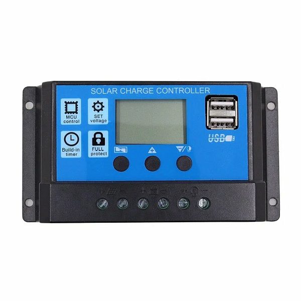
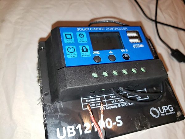
1. 10A PWM SOLAR CHARGE CONTROLLER. $12.99
Check THIS LINK first to see if there are cheaper ones on eBay.
This is the heart of our build. This device not only charges the battery, but it also keeps the battery at float voltage, so that means it can be left connected to the battery indefinitely without worry of damaging the battery from overcharging. It provides constant power to the load device (in out case a Raspberry Pi) and keeps it powered, so that when the sun goes down, the Raspberry Pi stays on.
The charge controller will automatically disconnect outgoing power to the Raspberry Pi is the battery voltage drops below 10.7 volts. This protects the battery from damage due to undercharging. This should not happen unless your power goes out for more than 14-20 hours, or if you are using a low wattage solar panel on a cloudy day.
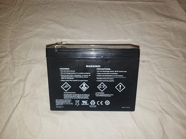
2. THE BATTERY $23.99
This is a high capacity Lead Acid battery relative to our Raspberry Pi 4B's power requirements. In my tests, this battery kept the Pi (at just above idle) on for 24.2 hours before the charge controller automatically disconnected the power to the Pi. At this point, the battery needed recharging.
3. 3A Buck Converter (With LCD). $5.75
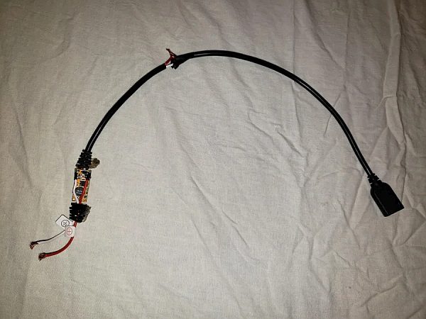
This device, called a “buck converter”, steps down voltage coming from a power source, such as a 12v lead acid battery, and converts it to 5 volts, the same voltage that all USB devices run on. I used to have one with a set voltage and an inline fuse, but I found the tolerances of the set voltage to be simply too wide. The new one is fully adjustable and even has a handy LCD to check on the output voltage. Simply turn the screw counter clockwise until it reaches 5.5 volts. You may need to strip back the USB C cable to attach the power leads directly to the output of the buck converter, unless you have a USB female adapter lying around.
IF YOU WANT GO SOLAR:
4. SOLAR PANEL– $78.50 – (Now $85, I suppose prices went up again.)
Please read:
Yes, this is a 100 watt solar panel. Complete overkill, I know. I used a 40 watt I had laying in my closet, but I cannot find any decent 40-50 watt polycrystaline panels which are priced below $70, which I would feel comfortable recommending to you, so for $78.50 you really can't argue against an extra 50 watts of power. Using this panel, you may even use two 10 AH batteries connected in parallel for double the runtime!
If you have a supplier which is able to provide you with a 40 watt or above solar panel for a reasonable price, feel free to buy that. Please be sure that the solar panel will output 18 volts, and that it is not internally regulated to 12 volts, otherwise the solar charge controller will not charge the battery.
I cannot recommend buying a folding solar panel, especially if you plan on building this project to run 24/7 as the folding solar panels available don't really have much in the way of a permanent mount; they're designed to be mobile.
DC POWER SUPPLY:
LAPTOP CHARGER $12.58
Yes, it is a plain old laptop charger. But do you remember how the charge controller was called a Solar Charge Controller? It was designed for power input from solar panels! It just so happens that solar panels put out the same voltage range (18-24v) as most laptop chargers! So this means that we can use the laptop charger to directly connect to our charge controller, in turn the battery and any connected loads. Feel free to use any old laptop chargers you may have laying around, so long as they do not exceed 25 volts and 10 amps. This is the setup I use.
ADDITIONAL ITEMS YOU MAY ALREADY HAVE:
5. FEMALE DISCONNECT – Amazon $8.59
These are the plugs that connect to the terminals on top of the battery. They are crimped to the 14 gauge wire which connects to the charge controller. Additional eBay link: Female disconnects – eBay (usually cheaper)
6. 14 Guage Wire. $18.49
This runs between the battery and the charge controller.
Please use your own wire or use an old extension cord, because buying a whole spool of wire which costs $18.49 if you'll only use it for one project seems way overkill, considering that you can often find wire at the hardware store for $0.39 per 12 inches, or even at the recycling center for free. Only use however much you need.
7. Optional: Waterproof ammo can – $12.99
All of the components I used fit well into this box I had lying around. You do not need to use it, but I would recommend it since it keeps things tidy.
(PRO TIP: You can also use lamp wire!)
TOOLS NEEDED:
Multimeter – Crimps (or pliers) – wire strippers – wire cutters (or scissors) – hot glue gun – electrical tape
Step 2: Diagram (For Reference)
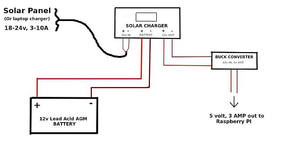
Examine the diagram associated with this step, and refer back to it as needed when assembling the parts. It shows how all of the different parts are to be connected, and where to connect the positive and negative wires. DO NOT and I repeat do not connect positive and negative wires in reverse. You will destroy your controller, and possibly your buck converter too. Trust me, I tried, and I fried.
Step 3: Solar Panel Setup
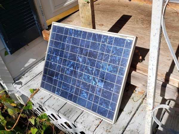
For testing purposes, you can set the panel angles towards the sun to check polarity and voltage. Once you have found an optimal spot to place it, you can secure it or permanently mount it. I will not be covering optimal mounting locations in this tutorial. I chose to mount the panel facing southwest on a blocked off chimney, as it was above the shadow line of the trees.
Do not get on a roof without proper safety equipment, training, or permission. Severe, permanent injury or death can result from a fall.
Once your solar panel is securely mounted, run wires to the location where your charge controller will be set up. I used an old extension cord for this task. Whatever wires you choose to use should optimally be rated above the maximum current of your solar panel.
Step 4: Begin Assembly: Preparing Wires
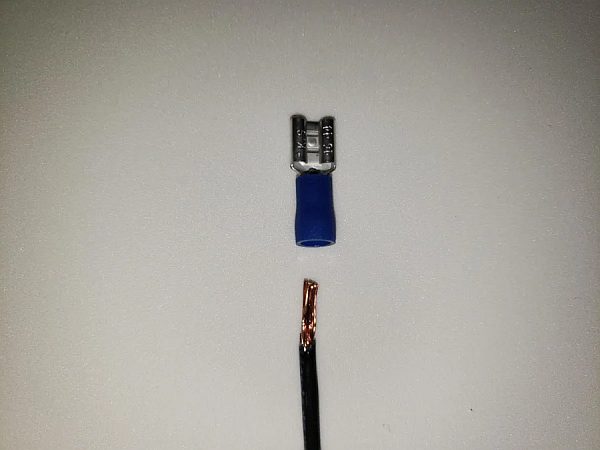
Strip the wire and crimp a female disconnect onto one end. Run the wires at your desired length to reach the bottom of the charge controller. These wires connect to the battery. I recommend labeling the positive wire so you don't get it mixed up.
As you will see in the next step, I glued the controller to the battery, so I only needed 2 feet (60 cm) of wire. Adjust according to your preferences.
Step 5: Optional: Glue Controller to Battery
I chose to hot glue the charge controller onto the battery casing.
This will make wire management easier, and generally keep things looking neat. Make sure to leave room underneath of the charge controller to connect wires.
This step is optinonal.
Step 6: Attach Battery Wires to Controller
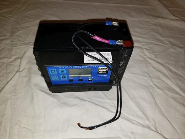
This is illustrated in the pictures. Simply attach your positive wire into the battery positive connector on the bottom of the controller. . On this model of solar charge controller, the battery positive is the third hole from the left. Repeat in likeness for the negative. Follow the terminal labels on the front of the controller.
If you did this correctly, your controller screen should turn on, displaying the battery voltage.
Please note, you may need to first loosen the terminal before inserting the wire. Use a phillips head screw driver. Tighten the terminal screw down onto the wire, turning clockwise. Wire connections should be snug, not exposing any of the wire. This could cause short circuits or sparks which will damage the controller or possibly start fires.
Step 7: Connect Solar Panel/laptop Charger.
SOLAR PANEL:
Following a previous step, you should already have run the wires from the solar panel to the location where your charge controller will be located. First, use a multimeter to assure which wire is positive, and then plug the two wires into their proper terminals on the left side of the controller and tighten the screws down. Assure that the wires are snugly in place and that there is no contact between bare wires.
LAPTOP CHARGER:
You may choose to cut off the end of the cord (the output end that plugs into the computer) and strip the wires back about 1/4 of an inch or 1-2 cm. Attach the wires into the correct set of terminals, on the left side of the controller. Tighten the connections down. Make sure there is no contact between bare wires.
Step 8: Attach Buck Converter
I chose to shorten the wires on both the input and output sides of the buck converter. You may do the same if you wish. Cut off the connectors on the input side of the buck converter, (The red and white wires that are labled) and strip the wires back 1/4″ (1-2cm) and finally attach them to the proper terminal connectors on the bottom of the charge controller. Tighten them, ensure the connection is snug. Check that no bare wires are touching.
I took off the plastic housing on the buck converter for testing purposes. Note that it did not simply snap back on, therefore I decided to just leave the PCB exposed for future testing. Ensure that you are getting 5v on the output side. you may need to sever the output USB cable to do this, which you would have already done if you decided to shorten it.
Step 9: Test Connections and Output Voltage
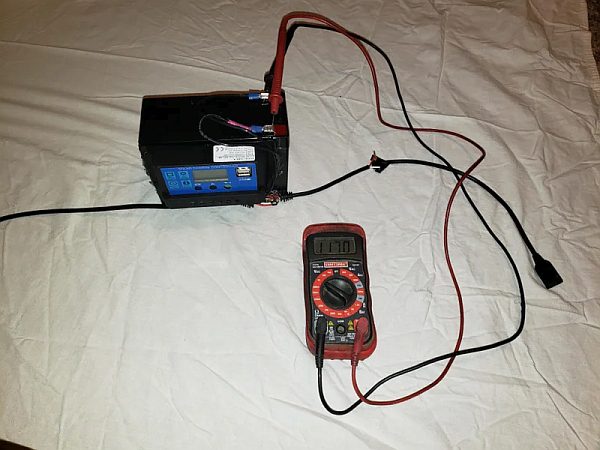
Test every connection and ensure that no exposed wires are touching. I would prefer that you make sure that there are no exposed wires period. Make sure the battery is putting out around 12v (This voltage is indicated on the charge controller screen) and that the buck converter is putting out 5 volts.
Finally plug the solar panel on a sunny day and watch the charge controller screen to see if the battery charges. There will be a small blinking arrow pointing to the battery on screen if it is charging correctly.
If everything checks out, you may choose to plug in your Raspberry Pi, or to try charging an old cell phone or other USB device first.
Please note that you should not test short circuit amperage with your multimeter as this will likely fry your buck converter or burn out the fuse in your multimeter. (Assuming it has a fuse)
tep 10: Additional Information
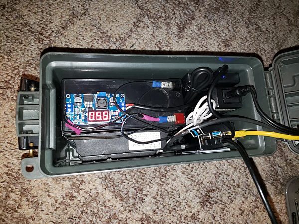
SHOVE IT IN A BOX!
I decided to shove everything into a plastic ammo can for ease of use, transport, and to keep any wires from getting bumped. I used a Plano case from Walmart that was originally $9. Whatever case you may decide to use, be sure to cut holes for passthrough ventilation. A case also gives you the ability to attach a fan that will cool the box actively. Personally, passive ventilation has worked well. If I was running a resource intensive program on the Pi, I would entirely recommend active cooling be installed.
CONTROLLER BUILT IN USB PORTS
A big question you may have about this project is “Why didn't you just use the two USB ports on the front of the charge controller?”
That is an excellent question. The USB ports provided on the front of the controller reportedly put out 2 amps, according to the advertisement. According to the user manual, they put out 2.5 amps. While 2.5a would be enough to power the Raspberry Pi 4B, I prefer to use the buck converter, because it provides up to 3 Amps of power passthrough. This also is the maximum cycle amperage that the 12v battery is rated for.
This gives out Pi plenty of room to breathe, and also allows other power hungry devices to be connected to the Raspberry Pi such as a hard drive.
Another reason is because I feel that the Buck converter in addition to the provided inline fuse offers more protection to the Pi, as opposed to the USB ports built in to the charger, which are not fused. You can certainly, however, use the built in USB ports if you want to. You may also use them to charge your cellphone in the case of a blackout, since this device is basically a special utility battery bank which allows pass-through charging.
REGARDING THE CHARGE CONTROLLER SETTINGS
I examined the poorly translated user manual which was included with my charge controller, and found that the default settings were just fine for my purposes. In this case, the default minimum-voltage-before-load-disconnect was set to 10.7, which let's be honest, no lead acid battery should be discharged below that.
The float charge voltage is set to 13.4 volts, pretty much ideal for an Absorbed Glass Mat battery such as the one used in this tutorial.
“What about those buttons on the front?” you may ask. Another excellent question. Simply, the only button you should worry about is the one to the far right. Pressing it will turn off any connected devices.
The button on the far left cycles through the different settings. Long pressing it for 12 seconds will cause the screen to flash. You can then use the middle and right hand buttons to adjust the settings. When done, long press the left hand button again. Here is a video detailing the process: How To Setup a Basic Solar Charge Controller | Quick Guide & Menu Overview