
The Problem:
I recently remodeled my home office and I now have a dedicated closet for my electronics (Server, NAS, AV Receiver, etc.) During the build I planned for heat remediation by installing an exhaust fan that dumps air from the closet into my adjoining office. However, the temperature in the closet hovers around 90°F (32°C), even with the fan on. Although this temperature is within hardware thresholds, it’s a bit warmer than I would prefer. To get a better understanding of my heat dissipation needs, I decided to monitor and record temperature fluctuations over several days to see what temperature ranges I was experiencing.
 Monitoring temperature levels is a perfect project for the Raspberry Pi. I have used an analog TMP36GZ low voltage temperature sensor before in an Arduino project but this would be my first attempt at using the Raspberry Pi’s GPIO pins. Unfortunately, after a bit of research, I discovered that my analog temperature sensor wouldn’t work with the Raspberry Pi’s “digital only” IO pins. While I could have prototyped a solution using an ADC and some spare components, I really wanted a simple build so I could just start coding on the Pi.
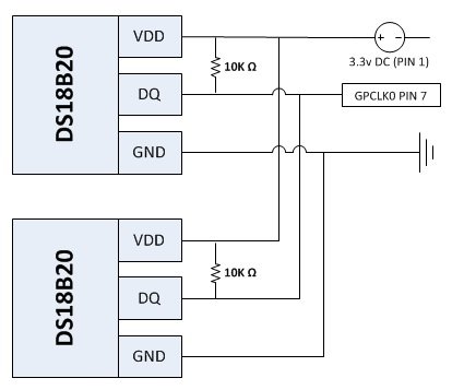
The solution to my problem was a DS18B20 Digital Temperature Sensor IC which I found on Amazon.com. The DS18B20 uses the 1-Wire communication bus which is perfect for the BCM GPIO4 pin (PIN 7) on the Raspberry Pi. Other caveats, you can work with the DS18B20 from the Linux terminal, and you can connect multiple 1-Wire devices, in series, to PIN 7.
The Build:
I had some spare CAT5e cable so I stripped and soldered 3 wires to the three pins on the sensor – orange for +3.3v, brown for ground, and green for data. Also, the DS18B20 requires a pull-up resistor between the power and data leads.
Then, I used electrical tape to insulate the exposed areas and I shrink-wrapped everything to protect the connections.
To the other end of the CAT5e cable I attached three female jumper wire cable housing connectors. These will principally be used for quick connections to a splitter rather than connecting directly to the Pi because I need to connect several devices to a single pin (specifically PIN7 for 1-wire).
Next, I manufactured three tiny Y-splitters (2 male to 1 female) to join the VDD, DQ, and GND lines from 2 sensors before connecting to the Pi.
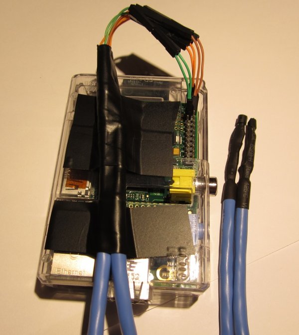
Finally, I made a second sensor and attached both to the Raspberry Pi using the following arrangement.
Here is the finished build. Note the three splitters are plugged into PIN1 (orange/3.3v), PIN6 (brown/GND), and PIN7 (green/data).
 The Code:
After connecting the DS18B20’s to the Raspberry Pi, you can interact with the devices using the below terminal commands. Note, your device IDs will be specific to your 1-Wire devices. In my case, my devices are 28-0000055f311a and 28-0000055f327d.
|
1
2
3
4
5
6
7
8
9
|
#Load the drivers
sudo modprobe w1–gpio
sudo modprobe w1–therm
#Show available devices (example 28-0000055f327d)
ls /sys/bus/w1/devices
#Read the output from the device
cat /sys/bus/w1/devices/28–<YourDeviceIdHere>/w1_slave
|
Here is what my terminal window looks like after running the above.
For more detail: Monitoring Temperature With Raspberry Pi