
More Raspberry Pi Electronics Experiments – Gertboard and Potentiometer-Controlled LED Cluster
One of the things which alerted me to the potential of the Raspberry Pi as an electronics control system was the announcement of the Gertboard before the Raspberry Pi was released into the market. When the Gertboard was announced for sale in November 2012, it was fully my intention to buy one, but a lack of money kept me from purchasing it at that point. The unassembled Gertboard kits soon sold out, leaving element14, who distribute the Gertboard, to decide to release an assembled Gertboard. This went on sale very recently, and shortly after release, I bought one from Premier Farnell’s Irish subsidiary.
The Gertboard, for the uninitiated, is an I/O expansion board that plugs into the GPIO header on the Raspberry Pi. Designed by Gert van Loo, designer of the Raspberry Pi alpha hardware, the Gertboard not only protects the GPIO pins from physical and electrical damage, but also provides a set of additional features. These include input/output buffers, a motor controller, an open collector driver, an MCP3002 ADC and MCP4802 DAC and an Atmel ATMega328P microcontroller which is compatible with the Arduino IDE and programming environment.
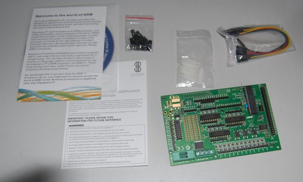
I was very impressed by the quick response from element14 after my purchase; my delivery came only two days after ordering and would have come even sooner if I hadn’t missed the 20.00 deadline on the day I had ordered it. The Gertboard was packaged with a number of female-to-female jumper wires, a set of jumpers, plastic feet for the board and a CD-ROM with a set of development tools for the ARM Cortex-M platform.
So far, I’ve only had occasion to test the buffered I/O, the ADC and DAC and the microcontroller; I still don’t have parts to test the motor controller or open collector driver. Aside from some documented peculiarities regarding the input buffers when at a floating voltage, including the so-called “proximity sensor” effect, things seem to have been going rather well.
The acquisition of the Gertboard gave me the impetus to really get down to trying to test my own expansions to the simple test circuits I had implemented before. One interesting application that I considered was to use a potentiometer to control a bank of LEDs in order to provide some sort of status indication.
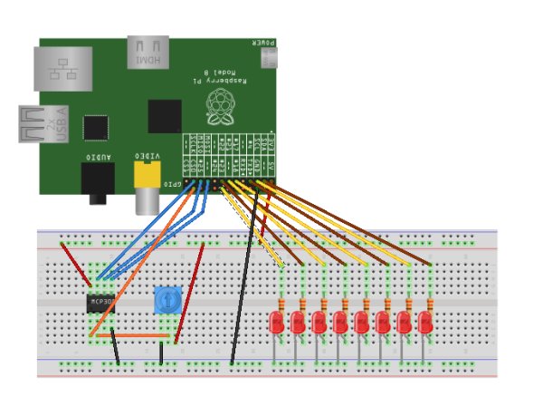
The following Fritzing circuit diagram shows the layout of this circuit without the use of the Gertboard; the onboard LEDs and GPIO pins lined up in a row on the Gertboard makes it slightly less messy in terms of wiring.
In this diagram, GPIO pins 0, 1, 4, 17, 18, 21, 22 and 23 are used to control the LEDs, although you could also use pins 24 or 25 without conflict with either the SPI bus – which is necessary for the MCP3002 ADC – or the serial UART on pins 14 and 15. However, this is a lot of GPIO pins taken up for one application, which may warrant the use of a shift register or an I2C I/O expander such as the MCP23008 or MCP23017 in order to control more LEDs with less pins.
In order to control this circuit, I took the sample Gertboard test software and modified it slightly. As the potentiometer is turned to the right, the ADC value increases to a maximum of 1023; therefore, the distance between each LED’s activation point should be 1023 divided by 8 – very close to 128. The LEDs will light from left-to-right as the potentiometer’s resistance decreases, with one LED lighting at an ADC reading of 0, two LEDs at 128, all the way up to all eight LEDs at 1023.
//
// Gertboard Demo
//
// SPI (ADC/DAC) control code
//
// This code is part of the Gertboard test suite
//
//
// Copyright (C) Gert Jan van Loo & Myra VanInwegen 2012
// No rights reserved
// You may treat this program as if it was in the public domain
//
// THIS SOFTWARE IS PROVIDED BY THE COPYRIGHT HOLDERS AND CONTRIBUTORS "AS IS"
// AND ANY EXPRESS OR IMPLIED WARRANTIES, INCLUDING, BUT NOT LIMITED TO, THE
// IMPLIED WARRANTIES OF MERCHANTABILITY AND FITNESS FOR A PARTICULAR PURPOSE
// ARE DISCLAIMED. IN NO EVENT SHALL THE COPYRIGHT HOLDER OR CONTRIBUTORS BE
// LIABLE FOR ANY DIRECT, INDIRECT, INCIDENTAL, SPECIAL, EXEMPLARY, OR
// CONSEQUENTIAL DAMAGES (INCLUDING, BUT NOT LIMITED TO, PROCUREMENT OF
// SUBSTITUTE GOODS OR SERVICES; LOSS OF USE, DATA, OR PROFITS; OR BUSINESS
// INTERRUPTION) HOWEVER CAUSED AND ON ANY THEORY OF LIABILITY, WHETHER IN
// CONTRACT, STRICT LIABILITY, OR TORT (INCLUDING NEGLIGENCE OR OTHERWISE)
// ARISING IN ANY WAY OUT OF THE USE OF THIS SOFTWARE, EVEN IF ADVISED OF THE
// POSSIBILITY OF SUCH DAMAGE.
//

#include "gb_common.h"
#include "gb_spi.h"

void setup_gpio(void);

int leds[] = {1 << 23, 1 << 22, 1 << 21, 1 << 18, 1 << 17, 1 << 4, 1 << 1,
	      1 << 0};

int main(void)
{
    int r, v, s, i, chan, nleds;

    do {
	printf("Which channel do you want to test? Type 0 or 1.\n");
	chan = (int) getchar();
	(void) getchar();
    } while (chan != '0' && chan != '1');

    printf("When ready, press Enter.");
    (void) getchar();

    setup_io();
    setup_gpio();
    setup_spi();

    for (r = 0; r < 1000000; r++) {
	v = read_adc(chan);
	for (i = 0; i < 8; i++) {
	    GPIO_CLR0 = leds[i];
	}
	nleds = v / (1023 / 8); /* number of LEDs to turn on */
	for (i = 0; i < nleds; i++) {
	    GPIO_SET0 = leds[i];
	}
	short_wait();
    }

    printf("\n");
    restore_io();
    return 0;
}

void setup_gpio()
{
    /* Setup alternate functions of SPI bus pins and SPI chip select A */
    INP_GPIO(8); SET_GPIO_ALT(8, 0);
    INP_GPIO(9); SET_GPIO_ALT(9, 0);
    INP_GPIO(10); SET_GPIO_ALT(10, 0);
    INP_GPIO(11); SET_GPIO_ALT(11, 0);
    /* Setup LED GPIO pins */
    INP_GPIO(23); OUT_GPIO(23);
    INP_GPIO(22); OUT_GPIO(22);
    INP_GPIO(21); OUT_GPIO(21);
    INP_GPIO(18); OUT_GPIO(18);
    INP_GPIO(17); OUT_GPIO(17);
    INP_GPIO(4); OUT_GPIO(4);
    INP_GPIO(1); OUT_GPIO(1);
    INP_GPIO(0); OUT_GPIO(0);
}
Filed under: Programming, Science & Engineering, Technology | Tagged: gertboard, raspberry pi | Leave a comment »
A Raspberry Pi Electronics Experiment – TMP36 Temperature Sensor Trials and Failures
I mentioned in my last post that I had received a Raspberry Pi electronics starter kit from SK Pang Electronics as a gift for Christmas, and between studying for exams, I have been experimenting with the components in the kit. Apart from ensuring that the components I received actually work, I still haven’t got much past the “flashing LEDs in sequence” experiments. I think I need a few more components to really experiment properly – transistors, capacitors, et cetera – but I have had a bit of fun with the components that I did receive.
Not everything has been entirely fun, though. One component, the TMP36 temperature sensor which I received with the kit, led to a struggle for me to find out how it worked. On the face of it, this should be – and if you test it without the full circuit that I first tried it with, is – one of the easier components to deduce the operation of. My temperature sensor is in a three-pin TO-92 package, with one pin accepting an input voltage between 2.7 and 5.5V, another connecting to ground and a third which has a linear output voltage with 500mV representing 0ºC and a difference in voltage of 10mV for every degree Celsius up or down from 0ºC. So far, so simple. The problem is that I made things rather difficult for myself.
The Raspberry Pi, unlike a dedicated electronics-kit microcontroller like the Arduino platform, doesn’t have any analogue input or output. In order to get analogue input or output on a Raspberry Pi, you need either an analogue-to-digital converter for input or a digital-to-analogue converter for output. This wasn’t a big deal; both the MCP3002 ADC and the MCP4802 DAC came with the SK Pang starter kit and I had just successfully tested the 10kΩ Trimpot that came with the kit with the ADC. My self-inflicted problems occurred when I thought (ultimately correctly) that the three-pin package of the temperature sensor looked like it would be an adequate drop-in replacement for the Trimpot. So, I plugged in the temperature sensor based on the schematics in front of me and tried running the program to read in and translate the readings from the ADC.
 As I started the program, I noted that I was getting a reading. So far, so good, I thought. Then, I decided to press on the temperature sensor to try adjusting the reading. At this moment, I noticed that the sensor was alarmingly hot. Disconnecting the sensor as quickly as I could reason, I thought to myself, “Oh crud, I’ve just ruined the sensor before I could even try it properly!” Taking action based on the directions given for TMP36 sensor use on the internet, I allowed the sensor to cool before plugging it back in – the right way around, this time – and tried the ADC translation program again.
I was still getting a reading, but this time, I was more wary; I did not know whether this signified that the correct reading was being read or not. With the aid of an Adafruit tutorial written precisely to aid people using the TMP36 with the Raspberry Pi, I decided to modify the ADC translation program to give converted values in the form of temperature readings. Another problem seemed to ensue – the readings I was being given were far too low for the room I was in. I attempted to find a solution on the internet, by reading forum posts, tutorials and datasheets, but little of this made sense to me.
Eventually, though, at least one of the sources gave me the idea to use a multimeter on the temperature sensor to test whether the output voltage on the middle pin was reasonable. I plugged the TMP36 directly into the 3.3V supply on the Raspberry Pi and tested the voltage over the input and output. It was showing as approximately 3.3V, so there wasn’t a short voltage on the temperature sensor itself. I then tested the output voltage on the middle pin, and this showed a reading much closer to the 20-22ºC I was expecting from my room at the time. As far as I could tell, the temperature sensor wasn’t damaged from the brief overheating that it had experienced. However, at this point, I had other things to do and had to leave my experimentation.
Eventually, though, I got back to experimenting with the TMP36 again, and tried plugging it into the ADC again. It was still giving the same low readings, and I still didn’t understand completely if the sensor, the ADC or the program I was running was at fault. I was at a loss to understand what was going on, so I shelved the temperature sensor experiments and tried understanding the code for the other components so that I could try my own experiments.
Some more looking on the internet pointed me more towards the answer I was looking for, though. The datasheet for the TMP36 suggests the use of a 0.1μF bypass capacitor on the input to smooth out the input voltage, but this didn’t really sound like the issue I was having – more it seemed like there was a low voltage going into the ADC. A forum post gave me an idea – try using a multimeter to test the voltage going across the TMP36 when it was plugged in with the ADC, and the output voltage from the sensor with the full circuit going. So, I did, and again, the temperature sensor had 3.3V going across it and about 740mV output voltage from the middle pin. I was perplexed, and tried testing the voltages across the ADC itself.
It was at this moment that one little sentence from the forum post gave me the answer – the problems with using the MCP3002 for reading in the voltage from the temperature sensor were linked to input impedance over the ADC rather than any problems with the temperature sensor. The ADC was working correctly in terms of reading in the value, and the temperature sensor was also working correctly, but because there was an impedance on the ADC – the voltage going across the ADC is 3.3V, but the voltage between the input pin and the channel read pin is, at least on my MCP3002, 2.58V – there were incorrect readings. A bit of modification to the ADC translation program, and I had the sort of readings that I expected both on the output voltage of the temperature sensor and the screen where the results were being printed.
Rather a long-winded set of tests for a simple problem, eh? I suppose much of the problem lies in my putting the cart before the horse and trying experiments with my only knowledge of electronics being my long-faded memories of secondary school physics. In any case, the problem was found, and a problem in my own lack of experience was also found, which I can start rectifying soon enough.
Filed under: Science & Engineering, Technology | Tagged: electronics, raspberry pi, temperature sensor, tmp36 | Leave a comment »
My first fortnight with the Raspberry Pi
The 12th of June was a good day for me. For one thing, I received the second semester results for my course to find that I’d received A grades in all three subjects and come close to perfect in C programming. For another, my Toolkit, the diverse set of computers which I own, gained another member in a new Raspberry Pi, bringing my computer collection up to eight.
The Raspberry Pi, for those who don’t already know, is an ARM-based single-board computer with a 700MHz ARM11 processor, 256MB of RAM, a powerful GPU and a very low price tag, on the order of £25 for the Model B version which includes a 10/100 Ethernet port and two USB slots in comparison to the single USB slot on the yet-unreleased Model A. Demand has been staggering, and after several months of waiting, I finally had my hands on a Raspberry Pi of my own.
Unfortunately, my worry that I had either bought an SD card which didn’t work or that my Raspberry Pi might be faulty prevented the first boot from being as exciting as it should have been, but once I had realised my own mistakes and resolved them, I had another working Linux system in front of me, ready to test. A few hours were spent loading some of my preferred software which wasn’t loaded onto the Debian image by default, including Emacs, but the Debian Squeeze image gave a remarkably complete starting system with enough programming tools to get going almost immediately.
Having failed to locate my HDMI to DVI lead which would give me a bit more flexibility when it comes to monitor choice – I don’t own any monitors with HDMI support – I resorted to the composite connection, which I’ve set up to provide 640×480 support – enough to show 80 columns in text mode and to show a couple of windows using X. It’s not exceptional, and compared to the full 1080p performance that the HDMI slot can deliver, it’s really quite awkward, but the provision of the composite socket was a good idea by the Raspberry Pi Foundation, giving the Raspberry Pi the ability to run on a fairly wide arrangement of monitors and TV screens.
My collection of computers means that I’m not exactly short of Linux PCs, so after doing a brief test of the GCC compiler and Python interpreter, I decided to begin looking for resources to learn something which the Raspberry Pi is well-suited for – ARM assembly language. Perplexingly, while resources on learning ARM assembly language are reasonably available on the internet, most of the resources on learning Linux assembly language seem to be related to the x86 architecture – an architecture with much uglier assembly language, with far less user-available registers and a CISC model which means that there are operations to learn with more variance between them than on the ARM’s RISC model.
I have managed to find sufficient materials to make a start, though, so I’ve managed to make some headway into learning how the ARM processor works, which will hopefully give me a bit more insight into how the processor works and how code can be effectively optimised. As the Debian Squeeze image for the Raspberry Pi comes with GCC as default, as any good, full Linux distribution should, the appropriate assembler was already present, and there are, of course, a lot of technical details about the ARM architecture’s instruction set available from ARM themselves. All I can really do of my own accord so far is to do simple arithmetic or bitwise logical operations, but everybody has to start somewhere.
I haven’t really tested the performance of the Raspberry Pi to its full yet, but I do have a somewhat similar embedded system with broadly similar specifications in my hacked Wii console, which also runs Debian Linux with the same LXDE desktop environment as on my Raspberry Pi. The Raspberry Pi seems to run more smoothly than the Wii running Linux, possibly a consequence of the greater RAM. There are a few slowdowns when loading Emacs on X, but Emacs doesn’t even load instantaneously on my dual-core desktop, so the slight pause is something I’m willing to tolerate. Anyway, the greatest strength of the Raspberry Pi is meant to be in its GPU, and I haven’t tested that yet, so my call on the Raspberry Pi’s performance will be more complete when I have a more full picture. So far, though, I can’t complain – it should serve the educational audience well enough to fit the programming tasks which the Raspberry Pi Foundation seem to have at the front of their minds.
Filed under: Technology | Tagged: raspberry pi | Leave a comment »
The Raspberry Pi: A project to shake up the stagnation of educational computing
As previous articles may have suggested, I’m a Linux aficionado, and have been for several years. I’ve been trying my hand at Linux systems for something like ten or eleven years, running through successive versions of SUSE Linux and openSUSE, later adopting Debian and Ubuntu on some of my other computers. Ultimately, my time with Linux has helped hone my computer skills, often requiring more of a technical mind when things go wrong than the equivalent Windows system, but feeling all the more satisfying when everything goes smoothly.
The readily-available command-line-based programming tools from the GNU Project have helped me learn more about the structure of the languages I’m learning than the graphical IDEs that I used on Windows. As Linux has evolved, the old methods of doing things often remain for a transitional period, allowing for a smooth transition as one sees fit without closing oneself off from newer applications. While it’s not yet a perfect alternative to Windows for the vast majority of users, Linux is often a better platform for learning how to use a computer technically than a comparable Windows or Mac OS X installation, for the freedom it allows, the easy extensibility and the ethos of the hobbyists it has grown up around.
For years, I have lamented the wilful ignorance that many people have towards computer technology when it isn’t handed to them with a flashy graphical user interface which aims towards the lowest common denominator. While I can understand that most users don’t want to be hacking C on a command line, and that there are places for people who do want to be doing this to learn, it is frustrating to see otherwise intelligent and capable people become brain-dead consumers as soon as they face a computer screen. I have no hesitation in asserting that most of their problems are a case of a total lack of interest rather than some inherent condition of computers to create fools out of intelligent people. Even in a world increasingly dominated by information technology, it seems to be fashionable to close one’s self off from computers as if they were some sort of magical artefact, and as if those that can use them well are practitioners of some sort of black art.
Educational systems at primary and secondary level have had trouble keeping up as well. Faced with a field of rapid evolution and even more rapid obsolescence, the education systems in the UK and Ireland, among others, have taken the same sort of “lowest common denominator” approach as many software providers. Education in computing most often takes the form of learning how to use office software, without any real provision for the teaching of programming techniques, nor of basic computer science techniques such as sorting, binary mathematics or such other useful principles. This isn’t just a theoretical matter either; many IT and other computing companies in the UK have reported a lack of educated staff in the fields of computer science, information technology and allied fields. Even Google’s chairman, Eric Schmidt, has lamented the lack of computer science education among the youth of the United Kingdom, a field which the British helped define in the 1950s and 1960s.
I am clearly not the only person displeased at the state of computer education at primary and secondary level. During the 1980s, during the golden era of home computers, before the near-monopoly of the x86 architecture and of Microsoft operating systems, computers booted up into BASIC interpreters, which although not capable of very much, defined programming as an inherent and integrated part of the computing process. Harking back to these ideas, a group of interested parties has formed a registered charity in Britain known as the Raspberry Pi Foundation, aimed at developing and producing a low-cost, tightly-integrated computer (the eponymous Raspberry Pi) on a motherboard small enough to be carried around easily and replaced inexpensively. The leader of the Raspberry Pi project, Eben Upton, works with Broadcom, which use British-designed ARM processors in their embedded designs, while David Braben, co-developer of the seminal game, Elite, for the BBC Micro, is another member of the foundation.
Together, the group has designed a computer containing a 700MHz ARM11 processor with an integrated GPU and ports for HDMI, composite RCA video and a 3.5mm jack. Two models will be available: the Model A contains a single USB port and 128MB of RAM, while the Model B adds another USB port, an additional 128MB of RAM for a total of 256MB, as well as a 10/100Mb Ethernet port for internet connections. A series of GPIO, I2C and other connectors is available as a separate header for both models, while an SD card slot provides the storage capacity for the operating system. The total cost of the computer, which has entered production and will soon be available for shipping, is projected to be £18 ($25) for the Model A and £22 ($35) for the Model B.
The cost is one of the greatest draws of the Raspberry Pi project, low enough to be easily replaceable if the unit is damaged beyond repair or to be used in robotics, integrated computing and other hobbyist projects. For that price, you get a surprisingly proficient piece of hardware, capable of running the likes of Quake III at 1080p, and capable of being a useful media player as well as an educational platform for programming, content creation, et cetera. The ARM processor architecture just happens to be one of the best for teaching assembly language, a skill which has recently largely been restricted to computer science and engineering courses. The GPIO and other headers allow the Pi to be used for robotics and automation projects at low cost, while the provision of the composite RCA connection allows old televisions to be used as screens in the absence of a high-quality monitor.
Such a device therefore addresses several concerns at once, while not really compromising on anything which is important for an effective syllabus of computer education. The hardware will soon be available; with Michael Gove recently announcing the scrapping of the much-maligned ICT syllabus to be replaced with a course with a greater focus in computer science, it remains to be seen if there can be a shift in mindset about technology away from treating it as a black box, and more as a platform for creativity and development, but I remain cautiously hopeful.
The Raspberry Pi’s homepage is available at http://www.raspberrypi.org/. The first batch of Raspberry Pi units, all Model B units designed for hobbyists and software developers, should soon be available for purchase. I, for one, am wishing for success in this endeavour.
Source: More Raspberry Pi Electronics Experiments – Gertboard and Potentiometer-Controlled LED Cluster