
This example shows how to use Raspberry Pi® hardware to interface to a motion sensor and control an external LED.
Introduction
Raspberry Pi target enables you to create and run Simulink® models on Raspberry Pi hardware. The target includes a library of Simulink blocks for configuring and accessing Raspberry Pi peripherals.
In this example you will learn how to create a Simulink model that reads the output of a motion sensor and performs a series of actions based on the detected motion activity. For this example, we will be using a Passive Infra-Red (PIR) motion sensor from Parallax® Inc. The PIR Sensor is a pyroelectric device that measures changes in infrared heat levels emitted by surrounding objects. When an object, such as a person, passes in front of the PIR sensor, the sensor sends a high signal to its output pin.
Prerequisites
- We recommend completing Getting Started with Raspberry Pi® Hardware example.
Required Hardware
To run this example you will need the following hardware:
- Raspberry Pi board
- PIR motion sensor from Parallax
- 1.8mm Red LED
- 270 Ohm resistor
- Breadboard wires (recommended)
- Small breadboard (recommended)
- Speakers or headphones (Task 3)
- A USB web camera (Task 4)
Task 1 – Connect the Motion Sensor and the LED to Raspberry Pi Hardware
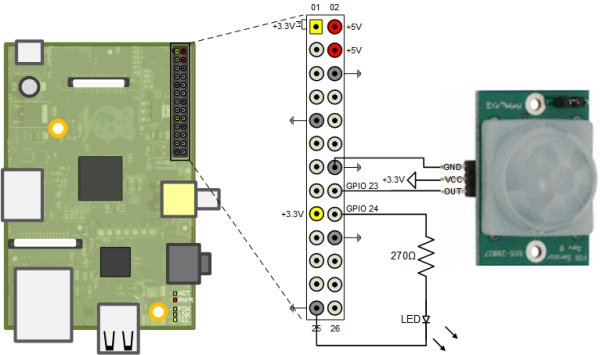
In this task, you will connect the PIR motion sensor and a red LED to the Raspberry Pi hardware. The sensor has three pins: VCC, GND, and OUT. The VCC pin will be connected to +3.3 Volt voltage rail and the GND pin is connected to the ground. The OUT pin is the logic signal indicating motion. This pin will be connected to a GPIO pin on the Raspberry Pi hardware as shown in the following schematics:
In the preceding circuit schematics, an LED has been connected to a GPIO pin. This LED will turn on whenever motion is detected. Note that the forward voltage of the LED used must be smaller than 3.3 Volts. We recommend using a 1.8mm red LED.
1. Interface the PIR motion sensor to the Raspberry Pi hardware as shown in the circuit diagram above.
2. Connect a red LED to the indicated GPIO pin of the Raspberry Pi hardware as shown in the circuit diagram above.
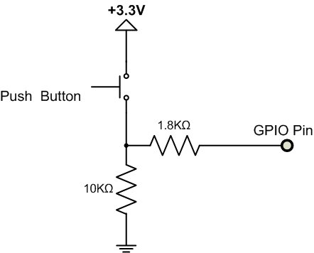
NOTE If you do not have the PIR motion sensor available, you can substitute a simple push button, as shown in the simplified circuit diagram below.
For more detail: Motion Sensor