
Update #1: Garage Monitor Memory Leak: Part 1.
Update #2: I should point out that the arm on the switch I ended up using bent so it stopped working after about a month of use. I really need to figure out a way to mount the magnetic switch instead. I added a rough parts list to the end of this article.
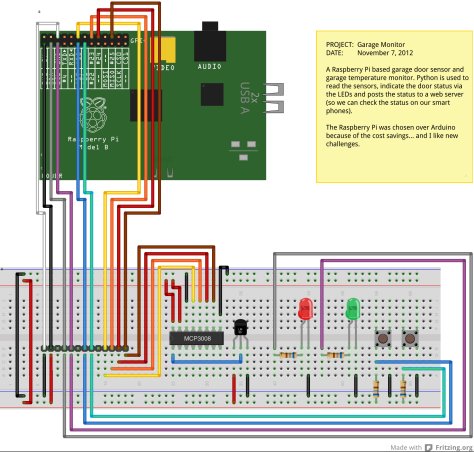
This project uses a switch and temperature sensor connected to a Raspberry Pi (revision 2 board) to provide the state of the garage to a personal web server. This allows my wife and I to check the status of the garage via a bookmark on our smartphones.
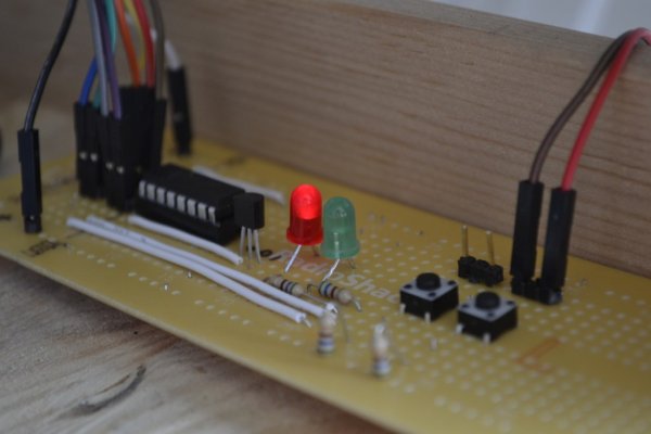
This is the first circuit I have created a circuit board for. I am proud of the results.
Adafruit Occidentalis
At the time of this writing my Raspberry Pi is running Adafruit’s Educational Linux Distro Occidentalis v0.2. Occidentalis is based on Raspbian Wheezy “but comes with hardware SPI, I2C, one wire, and WiFi support for our wifi adapters. It also has some things to make overall hacking easier such sshd on startup (with key generation on first boot) and Bonjour (so you can simply ssh raspberrypi.local from any computer on the local network)”
Python Script
The software running on my Raspberry Pi is coded in Python. The script runs at startup and checks every second (or so) for current status of the Closed/Open switches. When a change in state is detected, the current temperature is taken and the status is sent to a web service.
Web Service
I created a simplified “web service” in PHP which accepts the current door status (closed, open, or between) and the current temperature. The service logs the status and a timestamp to a file on the server.
Status Page
The current status is displayed by a PHP page which reads the last status from the server file and displays them. The background color of the entire page is changed to represent the current status (so the status can be known by a quick glance at my phone.
Custom Circuit Board
After getting the expansion circuit working on a breadboard, I picked up an Experimenter Printed Circuit Board at Radio Shack (Part 276-0170). I choose this board because is closely mimics the layout of a breadboard, so it made it easier for me to build a duplicate copy without worrying about making extra connections.
The Switch was Switched
I have had planned for months on using magnetic switches, but when I stuck the magnet on the door, I realized there wasn’t a clear place to mount the open and closed switches that didn’t interfere with the door track. Then I remembered the microswitches I had on hand as replacements for my pinball machine repair hobby!
I nailed this to a board and screwed that board into the wall at the bottom of the garage door edge. The extra long bar gets pressed down when the door hits the ground.
For more detail: My Raspberry Pi Powered Garage Monitor