
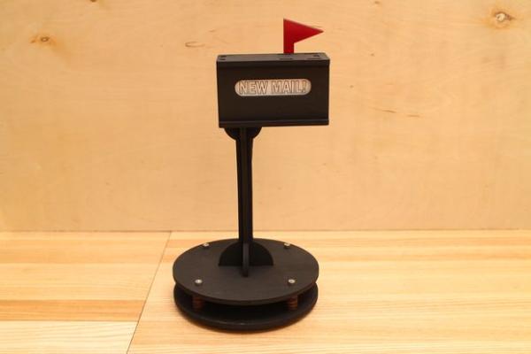
In this Instructable we will build a fun desk gadget to alert you when a new email arrives in your inbox.
Step 1: Materials
Materials:
Raspberry Pi (RadioShack #277-196)
protoboard (RadioShack #276-168)
(5x) 220 ohm resistor (RadioShack #271-1111)
(5x) white LEDs (RadioShack #276-017)
n-channel MOSFET (RadioShack #276-2072)
10K resistor (RadioShack # 271-1126)
Micro USB cable (RadioShack #26-2738)
2A USB AC power supply (RadioShack #55075817) web only
22 gauge wire (RadioShack #278-1218)
5mm thick Plywood
3mm thick Plywood
(4x) 1.5″ 8/32 machine screw
(4x) 8/32 nut
(2x) 4/40 nut
(2x) .75″ 4/40 machine screw
various paints
hot melt glue
Knowledge:
Read a schematic
Solder a simple circuit
Modify a program (no actual programming required)
Step 2: Setting up the Raspberry Pi: OS and Networking
We'll need to configure the Raspberry Pi before we get things up and running. I'll be making several web-connected Pi projects using the Netgear Wi-Fi adapter, so I've created a brief companion guide for setting up the wireless connection and links to properly setting up the Pi. Follow along here:
Connect the Raspberry Pi to the NetGear G54/N150
Step 3: Setting up the Raspberry Pi: Updating and Downloads
We'll need to download a few more things in order for Python to be able to properly check our inbox and use the GPIO.
Enter into the terminal:
sudo apt-get install python-dev
sudo apt-get install python-pip
sudo pip install feedparser
sudo easy_install -U distribute
sudo apt-get install python-rpi.gpio
Step 4: Setting up the Raspberry Pi: Python Code
Before we can use the device, we'll need to edit the Python code so it's linked to an email account. First, download the attached program ‘elights.py' and open it up in a text editor. You can copy it over to the Pi with a flash drive, but if you're new to Python, typing it manually will help you become familiar with the syntax.
Start up the GUI on the Pi with:
startx
Once the desktop environment has loaded, open up IDLE (not IDLE 3). Once the shell starts up, create a new window under File->New. Copy or type the program into the editor. You'll need to edit two lines of the program to contain your credentials. Where the red comments point to USERNAME and PASSWORD, change the default quoted words to match your information. USERNAME will just be the part of your email address before the @.
Hit ctrl-s to save the file. Be sure to keep the name as elight.py, as it needs to be exact for the next steps to work.
Once you've properly saved the file, open up the terminal (LX terminal program on the desktop). Type in:
sudo chmod +x email_light.py
This will turn our python program into an executable.
 email_light.py1 KB
Step 5: Set Up the Raspberry Pi: Final Touches
Now that we've got the program, we'll need to have the Pi run it automatically. To do this, we'll be editing one of the initialization files so that our program will run as soon as the Pi boots up and without having to log in.
Enter the following into the terminal:
sudo nano /etc/rc.local
You'll see a bunch of commented out text (prefixed by ‘#') explaining the file. Skip to the end of the text and type in:
sudo python home/pi/email_light.py &
Hit ‘ctrl+x' followed by ‘y' to save and confirm your edited file
This will run our python program when the Pi boots up. The ampersand at the end will make it run in the background.
Safely shutdown the Pi with:
sudo shutdown -h now
Step 6: Build the Circuit: Layout
To illuminate our little sign, we'll be using several LEDs in parallel. Since the output pins on the Raspberry Pi can only supply a few mA of current, we'll be using a power MOSFET as a switch to power them directly from the 5V source pin. We're using the IRF510, which is an N-Channel MOSFET, so when the Pi sends a logic HIGH signal to the MOSFET will connect all of the LEDs to ground.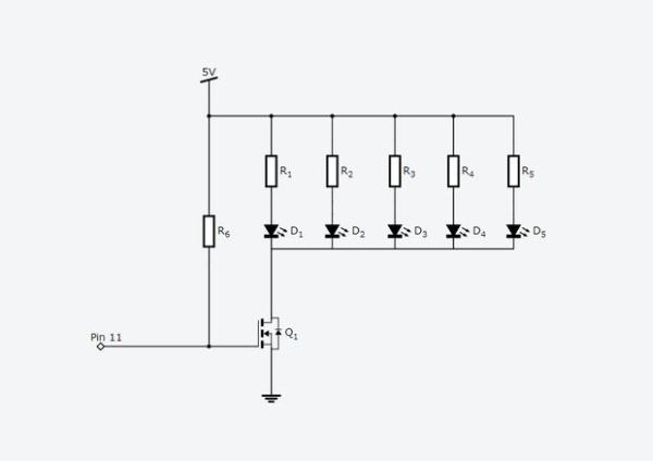
Step 7: Build the Circuit: Resistors
Place the five 220 ohm resistors spaced evenly across the board. Before clipping, bend the leads of the resistors that are towards the edge of the board so that they all connect and solder them in place.
Place the one 10K ohm resistor on the third column in and connecting to the power rail.
Step 8: Build the Circuit: LEDs and MOSFET
Place the LEDs with the anodes towards the resistors and the cathodes on the inner power rail.
Place the MOSFET in the upper right with the 10K resistor on it's leftmost pin.