
Bulldog Mote
One project currently being engaged in is the development of a new wireless sensor mote to
be used by California State University, Fresno. This new mote will be a brand-new device
using existing and up-and-coming technologies to be used by students to further research
efficient routing algorithms, device power consumption, network security, etc.
To build the new Bulldog Mote, several wireless protocols have been researched to
facilitate communication such as ZigBee, Bluetooth R Low Energy (BLE), LoRa R , etc. These different protocols have similar but varying capabilities that make each one conducive under different circumstances. For the case of the Bulldog Mote, the first design will likely have BLE wireless communication due to the prevalence of Bluetooth devices and the recently released Bluetooth Mesh protocol which is compatible with BLE.
This protocol was tested and experimented using the HM-10 BLE module and the results
are documented in the section titled: HM-10 BLE Communication Module.
Wireless Gateway Implementation
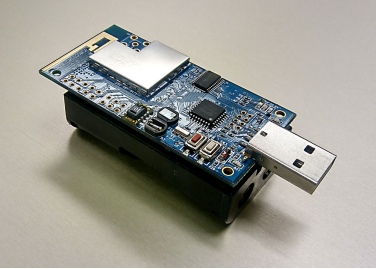
Tmote Sky Mote
A previously existing mote on the market is the Tmote Sky developed by the University of
California, Berkeley and produced by ADVANTICSYS. This device contains IEEE 802.15.4
compliant wireless sensor for mote to mote communication as well as different sensors to
measure light, humidity, and temperature all on one board. The mote can be powered by
two AA batteries, which can be inserted into the attached battery pack, or may be powered
through a USB connection.
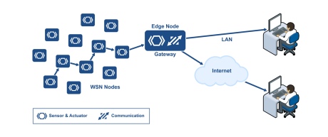
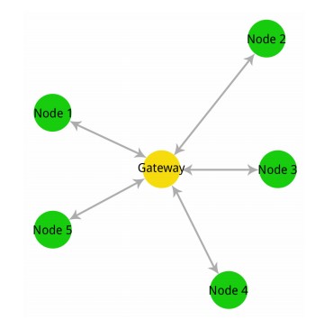
As versatile as the Tmote is, it lacks the capacity to display gathered data and TCP/IP
without being properly hosted. Implementing a gateway into a network allows all data to be
collected by the motes in a central location. It can then be transferred to another network,
such as an online database. A gateway is a portal between multiple networks in which they
are able to connect together. The image of a how a gateway bridges a wireless network
containing motes and a TCP/IP network is shown in Figure 2.
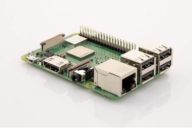
For this project, a small single-board computer, the Raspberry Pi 3b+ (RPi) was implemented
as the Gateway. This low cost, low energy, versatile computer was ideal for creating a
gateway necessary to connect motes to another network. With the proper operating system
configured on the Raspberry Pi (RPi), the Contiki program can be run to communicate with
the connected mote. This would function as a “sink” to collect the data transmitted by
neighboring motes. The RPi is equipped with Wi-Fi and Bluetooth capabilities, though is
unable to wirelessly communicate with the motes. By connecting a Mote directly into the
RPi via USB, the RPi is able to read the data that is being collected.
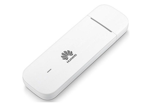
The RPi is a miniature computer capable of utilizing other additional components.
A wireless 4G USB dongle Huawei E3372 was implemented to allow for wireless mobile
telecommunication as another means for the gateway to communicate with a server. By
removing the restraints of the limited range of a Wi-Fi signal, the gateway and its mote
network can now be adapted to a much wider range of environments. The Huawei 4G USB
dongle used is shown in Figure 4.
To acquire a cellular connection, a SIM card and service provider is needed to be
purchased. Since the gateway will be transmitting very small packets of data to the web
server, data size could be minimal. It was decided to use the company SORACOM. Their
service charges a low upkeep cost of $0.06 a day, and $0.073 per megabyte of data. This
service is ideal for development to keep costs to a minimum. An image of the SORACOM
SIM card that was used is shown in Figure 5.
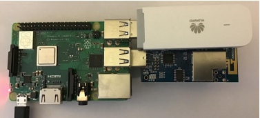
The completed gateway consists of the RPi with a Tmote Sky connected via USB as the
gateway mote. The Huawei USB dongle was used to allow for the mote network to function
in a remote area. A stable power supply was needed to power the gateway, though once
configured, a keyboard, mouse, and display was found not necessary. The finished gateway
is shown below in Figure 6.
Gateway Website
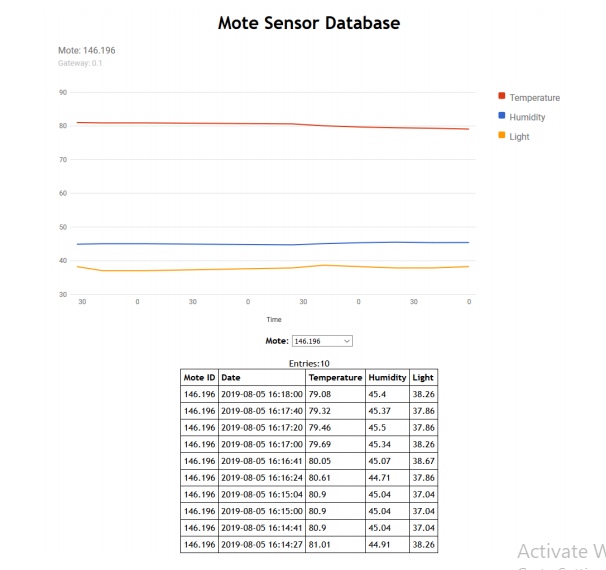
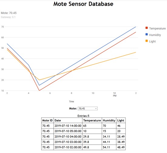
To properly view data being collected, the gateway sends data to a web database. A dynamic
website was created to display the mote’s sensor data, which maps it out over time. Cloud
services were considered, but dismissed with the high cost of features that were not necessary,
and could be carried out with a proper database. A snapshot of the website is displayed in
Figure 7 below, showing the data gathered from mote 146.196.
MANET Routing Protocols and Software
For WSNs to be effective in the field, many need to collect data a distance away from a
central node that connects to the internet. This makes data and packet routing essential.
For testing these algorithms, two software packages can be used: Contiki OS and NS-3.
Contiki OS
Contiki OS is a software package used to program the Tmote Sky, but in addition has a visual
simulator called Cooja as part of its installation. This operating system is an important step
to developing a new Bulldog Mote as the software is quite extensive and a great foundation
for developing new algorithms. This software however is specific to the Tmote Sky and a few
other motes, so an entirely new operating system will need to be written for the Bulldog Mote.
A basic routing algorithm was developed in the Contiki OS that was used as a starting
point to using the system. This new algorithm was a single-hop, ad-hoc wireless sensor
network made to facilitate any number of sensor nodes that can connect directly to a gateway
device. This program was simulated in Cooja and is shown in the section One-Hop, Ad-Hoc
Sensor Network in Cooja.
Despite the completeness of Contiki OS, there are several improvements that can be
implemented such as different structures of routing tables and additional features within
current routing protocols. Such improvements are in the process of being put in place and
tested.
HM-10 BLE Communication Module
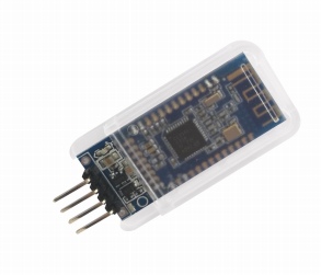
The HM-10 Module is a Bluetooth 4.0 Module produced by DSD Tech that includes Bluetooth
Low Energy (BLE). This module transmits over the 2.4 GHz ISM band like traditional
Bluetooth, however BLE uses considerably less power while still maintaining its effective
communication range. This makes BLE a viable option for IoT communication between
devices.
Overview
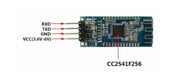
The BLE device communicates with a host microcontroller using UART. Depending on the
supplier the device is purchased through will determine the number of pins. For this tutorial,
the four middle pins will be used: RXD, TXD, GND and VDD
The commands to control this device have to be understood before it is plugged into a
microcontroller. To do this, an FTDI module can be used to connect the UART pins of
the HM-10 directly to a computer. There, a serial connection can be established with the
module and will give the user an easier time testing and debugging commands.
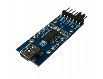
Any FTDI module will work, but be sure to purchase one with a genuine FTDI chip.
Most computers have firmware installed already that will make these devices plug-and-play
ready. However if the FTDI chip is not a genuine one, the modern firmware will be able to
tell and break the counterfeit chip, rendering it unusable.
The FTDI component used here is the SH-U09F, produced by DSD Tech as well.
The current drivers should be downloaded and installed before plugging the FTDI component
into the computer. The current FTDI drivers can be found at http://www.ftdichip.com/
Drivers/VCP.htm. There you can select the correct firmware for your operating system.
Once installed plug the device into your computer. The SH-U09F module here uses a micro
USB cable to connect to the host computer.
After the computer finishes configuring the FTDI module, unplug the device. Next the
FTDI module will be connected to the BLE module. The HM-10 device uses 3.3 V logic and
power, so on the SH-U09F module the jumper between the 5V0 pin and JP pin should be
changed to connect the 3V3 and JP pins instead. This changes the logic and VCC voltages
to 3.3 V. Next, the pins of the devices can be connected with jumper wire. The following
diagram should be followed:
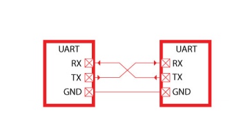
In UART communication, the receive line (Rx) on one device is connected to the transmit
(Tx) of the other, and visa-versa. VCC and GND should also be connected.
Once connected, a serial communication program can be used to send and receive data
from the user’s computer through a connected USB to the end device on the other side of
the FTDI module. The program used here to send and receive the UART data is Realterm:
Serial Terminal: https://realterm.sourceforge.io/index.html#downloads_Download.
Go to the link and click the download option at the top of the page to get the install
executable.
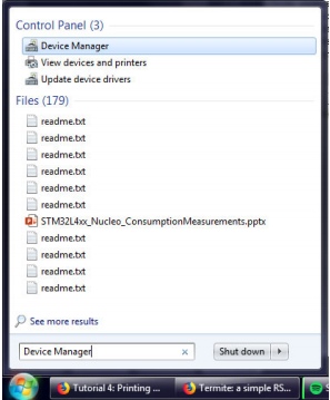
Once installed and opened, the program will connect automatically to a device with a
COM port. So plug in the USB of the FTDI module again, then open the Device Manager
by clicking the Start menu, then type Device Manager in the Search text box. Open the
Device Manager once it pops up.
Once opened, go to the Ports list to identify the COM number of the FTDI module. In
this case it is COM11.
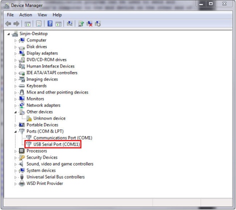
If there are many devices connected and it is difficult to tell which is the correct one,
then right click on them one at a time and go to Properties. Under Manufacturer should
be FTDI for the correct module.
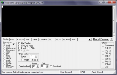
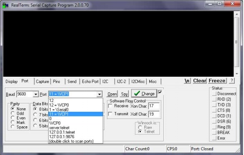
The first tab displayed in Realterm is just how the serial information is displayed. Leave
the Display As option as ASCII. Next, under the Port tab, select the correct port number
for the FTDI device and a Baud of 9600. Then click on the Open button to connect to the
module.
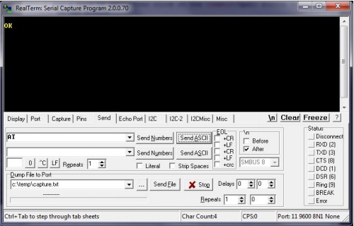
The FTDI device will now be ready to talk to. To start, click on the Send tab. There
will be two identical lines with a text input and buttons reading Send Numbers and Send
ASCII. Either of the two lines can be used to send data. There will be cases where you’ll
want to send raw binary/hexadecimal data to the device where the Send Numbers will be
useful. But for configuring the FTDI module ASCII encoded characters are what we need.
Also, to have FTDI responses on separate lines, click the After check box in the \n section.
Otherwise all of the responses will run on the same line.
Now the connection can be tested. In the text box type “AT” (without quotes) and
click Send ASCII. If the connection is successful there should be a response of “OK” in the
window.
HM-10 Module Configuration
Some default settings in the HM-10 module need to be changed after the module is wired
up and communication is verified in Realterm.
While in Realterm, type: “AT+IMME?”. If the response is “OK+Get:0”, then type
“AT+IMME1” to change the settings. This setting is used to tell the module to start
in command mode or work mode when the device starts up. In command mode (changed
by sending “AT+IMME1”), the component will only perform what the user asks based on
the AT commands. In work mode (“AT+IMME1”), the device will automatically perform
actions like connecting to neighboring devices, enabling discovery, etc. based on its current
settings on start up.
Next, we’ll want to see the messages that the device displays, so the next command will
turn on notifications: “AT+NOTI1”. Then, type “AT+NOTP1” to show the MAC
addresses related to the notification.
The HM-10 device likely has a default name (not the same as the MAC address). So
give the device a unique name by typing “AT+NAME[name]” where “[name]” is a
string. For example, if you want to name the device Bulldogs, then the command would
be “AT+NAMEBulldogs”.
Next, all Bluetooth Low Energy devices use some UUID value to identify what type
of information to expect in a standardized manner. To change the UUID value sent the
command: “AT+UUID[uuid]” where “[uuid]” is a valid UUID value in hexadecimal with
a hexadecimal prefix. For example, the UUID value 0x181A is the Bluetooth assigned number
for the Environment Sensing service. For more information on the Bluetooth protocol, read
the Bulldog BLE Handbook (coming soon).
Similarly, the service characteristic value can also be set on the HM-10. Under Environmental
Sensing Service there are several characteristics, one of which is Temperature with a UUID
of 0x2A6E. Use the command “AT+CHAR[char]” where “[char]” is the UUID value of
the characteristic to set the device’s characteristic.
Something to keep in mind is that when two HM-10 modules are connected to each other,
no AT-commands will be valid until the connection is broken. This can be done manually by
simply typing “AT”. The module should return “OK+LOST” when successfully disconnected.
Connecting Two HM-10 Devices
Two HM-10 devices can be connected together once the settings listed previously are changed.
Actually the devices could be connected prior to running those commands, but to save a
head-ache or two its advisable to run above commands first.
Multiple instances of Realterm can be run on the same computer so this process can
be completed on a single computer with two HM-10 devices connected to it. Whether you
decide to connect the other HM-10 to the same computer or not, perform the same steps
in the Overview and HM-10 Module Configuration sections of this document to set up the
second FTDI and HM-10 device separately.
Once both devices are setup and connected to the computer, then they can be paired
and bonded. To do so takes a few steps.
First, one device must be selected as the master and the other the slave device. In
Bluetooth Point-to-Point protocols, the slave device is the one that advertises its presence
and the master device is the one that makes the connection between the two devices.
To set the master/slave roles for each device use the command “AT+ROLE”.
Setting up Slave Device
To change the role of the module to a slave use the command: “AT+ROLE0”. Doing
this starts the module advertising its presence to BLE master devices. As a note, some
datasheets call the slave device the Peripheral Node.
Next, to change the interval in which the slave sends an advertisement use the command:
“AT+ADVI[P1]”, where [P1] is a value 0 through F and represents different time intervals
in Table 1:

The default value of 1285 ms is fine for our purposes.
Also to keep in mind, there are different advertising types under the “AT+ADTY”
command. The default allows advertising, scanning response and makes the device openly
connectable. To set the device back to its default type use: “AT+ADTY0”.
Lastly, some device won’t advertise unless the advertising data flag is set. To do this the
AT+FLAG command is used. Type “AT+FLAG0” and click Send ASCII. This command
can use values from 0 through FF, however using any value will get the device to advertise.
Now the slave device is advertising its presence and ready to be connected to.
Setting up Master Device
Setting up the master is a little simpler than the slave device. The command to set the device
to master is “AT+ROLE1”. The master is also called the Central Node in some datasheets.
Once set the device can immediately begin scanning for slave devices. Type “AT+DISC?”
to do so. If the slave is configured correctly the terminal for the master should read:
“OK+DISCS” (starting discovery), then “OK+DIS0:[MACADDR]” (where [MACADDR]
is the MAC address of the slave module), and finally “OK+DISCE” (for ending discovery
process). Likely all of these messages will be on the same line.
If there were multiple BLE slave devices available and in range there will be a
“OK+DIS1:[MACADDR]”. The important thing here is the value after OK+DIS. This
value represents the array index of the connectable BLE devices.
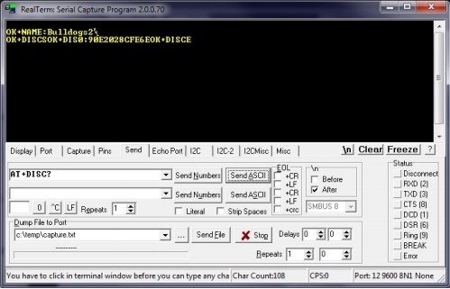
Discovery Connection
From Figure 17, the slave device is identified by “OK+DIS0:90E2028CFE6E” meaning
that the device with MAC address 90:E2:02:8C:FE:6E can be connected to using index 0. So
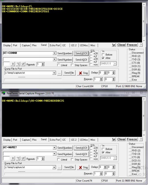
now the master can connect to this discovery device using the command “AT+CONN[DISC]”
where [DISC] is the array index. So in the case of Figure 17 the command would be
“AT+CONN0”. Doing this connects to the slave device and shows in both devices
terminals that they are connected to each others MAC addresses.
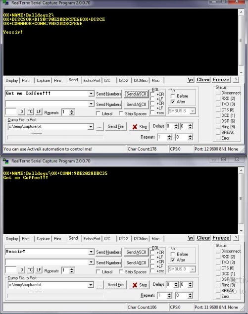
Now simple strings or numbers can be transmitted from slave to master and visa-versa.
In transmit mode, none of the AT commands will be recognized except the “AT” command,
which disconnects both devices.
Note: Once the slave device is disconnected the advertising flag needs to be set again before it can
be discovered.
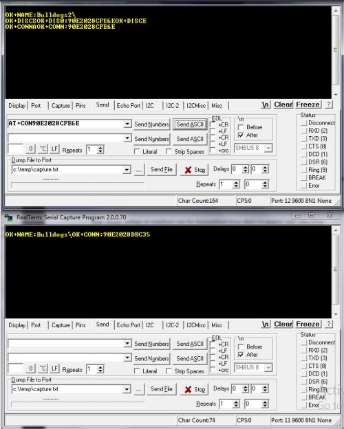
When connecting to a device its sometimes more desirable to connected to a device based
on its MAC address instead of discovery array index. The command “AT+CON[MACADDR]”
can be used to so this from the master. The discovery command should still be run first to
know if the slave device is available to be connected to first.
Connecting to HM-10 from Android Phone
In the last part, two HM-10 devices were connected, one being the master and the other the
slave. In this part, one HM-10 module will be used as a slave device and a smart phone
will be used as the master device. This part completely depends on the capabilities of your
smart phone. Make sure your phone has BLE capabilities to be able to do this.
If the phone does have BLE capabilities, the nRF Connect can be downloaded from the
Google Play Store. nRF Connect is an app by Nordic Semiconductor used to connect and
communication to any BLE device.

First however, one of the HM-10 modules should be set up as a slave device as shown
in the last section. In addition, the UUID for the slave device’s service and characteristic
should be configured as described in the HM-10 Module Configuration. Make sure to reset
the module after making changes to apply them using the “AT+RESET” command.
Once the slave device is set up and advertising its presence, the Android device can detect
and connect to it. To do so, install and open the nRF Connect app. If the Bluetooth adapter
is disabled it there will be a red bar instructing you to enable it.
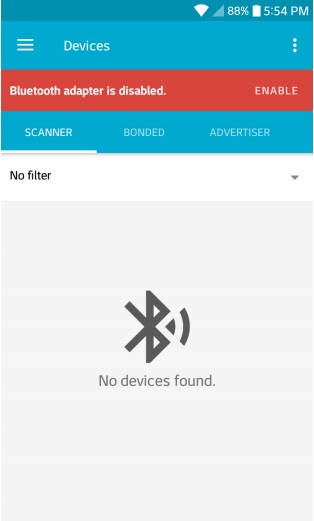
Once enabled, click the Scan button on the top right. After a moment, the HM-10 device
should show up with its name.
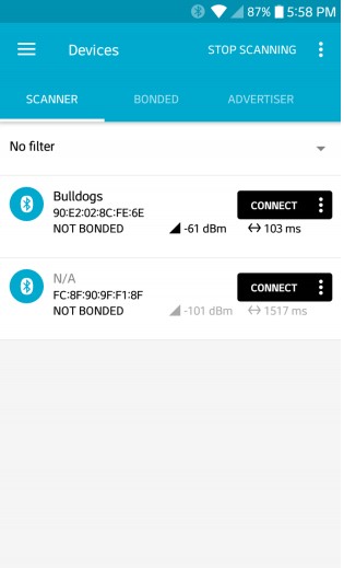
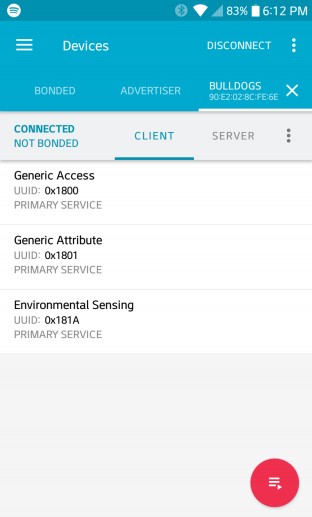
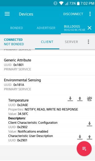
Click on the Connect button on the HM-10 device. Doing this will open a new tab with
the name of the module. In this tab there are three main services, two generic services and
one Environmental Sensing. Click on the Environmental Sensing service. If the UUIDs were
set up correctly, the values used in the configuration were for the Bluetooth Environment
Sensing Service (ESS) and Temperature Characteristic within the ESS.
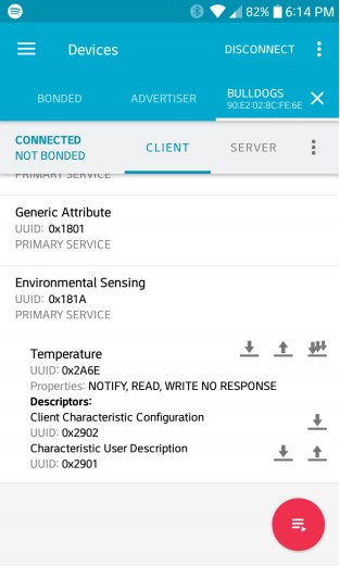
However, there is no data for the temperature reading yet. We don’t have an actual
temperature sensor connected to the BLE module, so we’ll have to fake it for now.
The temperature value can be transmitted from Realterm in the form of raw hexadecimal
values. Bluetooth gives specifications for formatting data for all characteristics. The ESS
Specification for the Temperature Characteristic allows a degree resolution down to 0.01◦C.
Also, the data type of the value is an sint16, or 16-bit signed-integer. To fix the decimal
point problem that would be lost in using a integer the temperature value needs to be
multiplied by 102 before being converted into signed-integer. So a temperature reading
of 34.56◦C would be 3456 and 0x0D80 in hexadecimal. Also, signed-integers used Two’s
Compliment to represent negative values. Thus, a temperature reading of -10.35◦C would
be multiplied by 102 and converted to Two’s Compliment to get a result of 0xFBF5.
So lets use the temperature value of 34.56◦C to send to the Android device connected to
the HM-10. In Realterm we can send these values in their signed-integer, hexadecimal form
with a couple things to consider. During the UART transmission, the Endianness of the
bytes of the numbers are reversed, so the byte order will need to be fixed manually. Also in
Realterm, each byte has to be expressed individually with a prefix, so 0x0D80 would need to
be sent as 0x0D and 0x80. And if we take into consideration the byte reversal then 0x0D80
becomes 0x80 and 0x0D.
So with this in mind, go to Realterm and in the Send tab, type “0x80 0x0D” in the
input box. Then instead of clicking Send ASCII, click Send Numbers instead to send the
raw hexadecimal values.
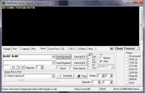
Now checking the Andriod device, it can be seen that a Value line appears with the
temperature reading of 34.56◦C:
Wireless Gateway Implementation
Gateway Operating System and Environment
Using the RPi required a different environment than the default Contiki OS. The Linux
distribution, Ubuntu-Mate was selected since it was compatible with the Contiki system,
and the architecture of the RPi. The operating system allowed for a desktop environment
which was user friendly, while also having the option to removing the Graphic User Interface
(GUI), for an even lighter system to preserve resources.
The Operating system was saved as a custom operating system so that the installation
does not need to be performed for each of the gateways. The following steps were taken to
properly install a fresh operating system and environment for the gateway.
Required hardware:
• Raspberry Pi 3 B or Raspberry Pi 3 B+ (minor testing shows that a 2B model may
work)
• Micro SD card (At least 8 gigabytes, 16+ gigabytes recommended)
• Separate computer with the ability to write to a Micro SD card
• Mouse, keyboard, and display for RPi
Installation
- Download the Ubuntu Mate operating system image for the Raspberry pi aarch32
architecture (NOT aarch64) from https://ubuntu-mate.org/download/. - After downloading the image, the program “Rufus” can be downloaded and used to
burn the image to a micro SD card. Putting the micro SD card into the pi and powering
it on begins the installation process. - Once the OS was installed, the installation of Contiki can be installed following the
guide at: http://anrg.usc.edu/contiki/index.php/Installation
While installing the packages for the OS, one of them was not found therefore the
others were not installed. Following the error provided and the command should be:
sudo apt-get install build-essential binutils-msp430 gcc-msp430
msp430-libc msp430mcu mspdebug gcc-arm-none-eabi openjdk-8-jdk
openjdk-8-jre ant libncurses5-dev
Once completed, the hello-world program was implemented to test for other errors:
http://anrg.usc.edu/contiki/index.php/Hello_World
There should not be errors during the first half, though the second half will give
errors. If there is a permission issue, put sudo in front of the code.
Instead of following the instructions provided about putting in a new “serialdump-linux”,
do the following commands using the terminal.
(a) Navigate to the following directory contiki/tools/sky using: cd contiki/tools/sky
(b) Delete the file serialdump-linux using: sudo rm serialdump-linux
(c) Rebuild the file using: make serialdump
(d) Check to see if the file created is named serialdump-linux using: ls
(e) If it’s not, then rename it to that by using: mv serialdump serialdump-linux
(f) Change the privilege of the file using: sudo chmod 775 serialdump-linux
(g) Use the command: sed -ie ’s/(ifdef O )SYNC/\1DIRECT/’ serialdump.c
(h) Navigate to the following directory contiki/examples/hello-world using: cd && cd
contiki/examples/hello-world
(i) Retry running the program using: make TARGET=sky hello-world.upload login
- The program should now run properly off of the Sky Mote, as well as the other
programs
Contiki Program
The Contiki program created is saved and ran on all of the motes including the gateway
mote. This program was based off of Contiki’s broadcast example, though was altered to
collect data from the sensors.
The program example-broadcast.c can be found in Appendix A, which can replace the
file located in the directory: contiki/examples/rime/example-broadcast.c. Once the file is in
the proper location, the following steps should be completed to save the file to each of the
motes, using a computer with Contiki and its new program installed, or the gateway.
- Plug the mote into the USB port.
- Open up the terminal (Ctrl+Alt+T).
- Navigate to the directory where the file was saved using the command: cd
contiki/examples/rime - Save file to the mote: sudo make TARGET=sky example-broadcast.upload
Once the process is completed and no errors have appeared, the mote can be disconnected
and these steps can be repeated for all of the motes in the network.
- The last mote that needs the program should be the gateway mote (the one that
stays connected to the RPi gateway). To test the mote network and view the data
in the present terminal, the following command can be used: sudo make TARGET=sky
example-broadcast.upload login
This programs main functionality was to establish and test communication between the
mote network and a web server. More complex programs, implementing more advanced
protocols can be constructed based off of this example.
Gateway Program
The purpose of the gateway program is to automatically make the connection from the
gateway to the web server, and run the Contiki program on the mote. Since the motes
lack the capability to store their own collected data, the RPi must read what the mote is
collecting, writing it to its own location, while simultaneously reading from the location to
send the web server. The python program written can be viewed in Appendix B. The file
location does not matter, though to keep things simple, should be saved to the desktop. The
desktop is where the motes data will be written in a file created by the program.
Inside of the program, there is a comment stating where the database information needs
to go. For security reasons, the database used to develop this project was not included, and
replaced with “x”. There are two ways about this, the web server can be created on the
users localhost, or a website and hosting can be purchased and configured.
Web Server
While mote networks have the opportunity to be implemented in remote areas, being able
to view data in these remote areas are not ideal. A web server was created to view the data
collected at the gateway, so it can be viewed in another location. Data was collected and
transmitted from the gateway, then sent and organized within a web server’s database. The
database was designed with the structure shown in Figure 27.
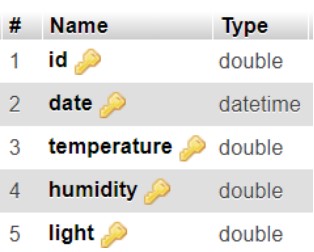
The id column is where the motes address identification is stored, each mote has its
own individual ID which it can be identified inside of a network. The next column is data,
which contains the year, month, day, hour, minute, and second that the gateway received
its data from a mote. The last three columns are Temperature, Humidity, and Light, which
is the sensor data that the motes have collected. Although the data may not vary over time
depending on how often the motes transmit, the date will always be incremented in time,
allowing each post to the database to be unique and avoid errors.
An important feature the web server needed was that it was dynamic, to allow for motes
to be added or removed to the network without needing to change any code. When viewing
the web server, the data shown is from the most recent updated mote. Its mote ID is
displayed at the top of the page, along with its designated gateway ID (which was a static
address given). The chart displays the sensor data stored in the database from that mote
ID. A snapshot of the initial home page is shown in Figure 7 above.
Towards the bottom of the page there is a drop down list, which asks the user to “Select
a Mote”. Selecting the drop down list displays all of the motes address IDs in the database
as shown in Figure 28.
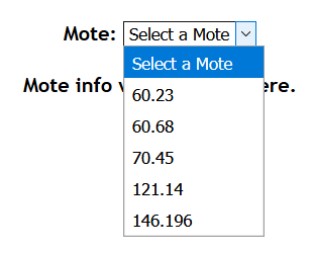
Once a mote is selected from the list, the chart is updated to display its sensor data, as
well as a list of all entries being displayed at the bottom as shown in Figure 29.
One-Hop, Ad-Hoc Sensor Network with Cooja
Overview
In some instances when routing data in a Mobile Ad-Hoc Network (MANET), all relevant
peripheral nodes are a single hop away from the gateway device. In such instances, algorithms
like Ad-Hoc, On-Demand Distance Vector (AODV) and Dynamic Source Routing (DSR) can
be more complex and computationally intensive than necessary.
Data routing in a single-hop network is far too simple to require such algorithms, so this
single-hop sensor network was developed as a simple solution. This program utilized the
broadcast and unicast features of the Contiki OS on the Tmote Sky.
Peripheral Node Gateway Detection
Each peripheral sensor node needs to be able to transmit its sensor reading upstream to a
gateway device. This allows the network to publish its data to some useful end whether that
be on the internet, server or other device to read and analyze the data. In this case, since
all the sensor nodes are within range of the gateway they can communicate directly.
However the devices doesn’t know which of their neighbors is the gateway. So to
determine where to transmit its data, each node will broadcast a message identifying itself
as a leaf node (or peripheral node). The broadcast message will be assigned a type of
BROADCAST TYPE LEAF TO PARENT. This will help other nodes identify the type of broadcast
messages being sent out.
All other leaf nodes will ignore these types of messages, since they are specifically for the
parent node. When the parent or gateway node receives this message however, it will keep
track of address of the node and unicast an acknowledgement (ACK) back to the node that
sent the parent request. This message is then received by the leaf node and the parent’s
address is recorded. Then the leaf node can freely transmit data to the parent as frequently
as it needs to.
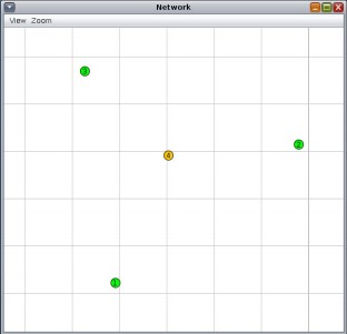
Simulation
Cooja was used to simulate this algorithm after it was implemented using Contiki OS. Figure
31 shows the node placement in the simulation. Nodes 1, 2 and 3 are the leaf nodes (green)
and node 4 is the gateway node (yellow).
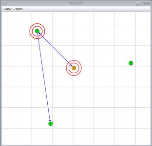
Once the simulation begins, a message log displays the activity of messages of each node
and the Network window begins showing messages being sent and received by each node
(Figure 32). The message log is shown in Figure 33.
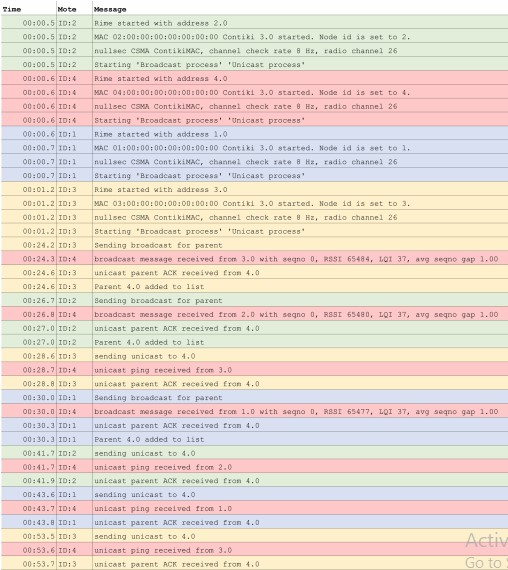
Simulation Results
Referring to Figure 33, whenever a node broadcasted a message for a parent, the parent node
would send an ACK in response. Broadcast parent requests can be seen at times 00:24.2
(node 3), 00:26.7 (node 2) and 00:30.0 (node 1). Each of these messages were acknowledged
at times 00:24.6 (node 3), 00:27.0 (node 2) and 00:30.3 (node 1). Then after each ACK
was received, the leaf nodes stored the address of the parent, which in the simulation is 4.0.
After each node logs the parent’s address, it waits a random period of time to send a unicast
message back to the parent (at times 00:28.6, 00:41.7 and 00:43.6). These message are also
acknowledged by the parent at times 00:28.8, 00:41.9 and 00:53.7.
These results show that the leaf and parent nodes successfully demonstrate this algorithm.
The leaf nodes always start by attempting to find the parent through broadcasting requests
and successfully ignore other parent requests from other nodes. The parent nodes correctly
identifies these requests and acknowledges them, allowing leaf nodes to continuously send
data (in the case of the simulation, the leaf only sent PINGs to the parent). In turn each
ping is acknowledged by the parent.