
Octopod, a uniquely shaped full automation system that allows you to monitor your industry and keep security with AI and smart RFID locks.
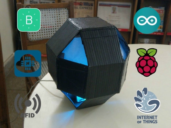
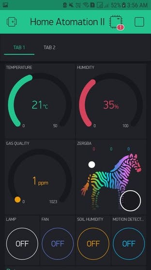
There are many IoT automation projects out there, but trust me there is nothing like this! Octopod is made using NodeMCU (MAX32620FTHR or Arduino MKR 1010), Arduino Uno, and Raspberry Pi 3. Octopod allows you to make your home smart. Octopod sends you a variety of data like temperature, humidity, and gas quality inside your home/office/ industry. Octopod sends you notification whenever it detects any sort of motion inside and tells you when you need to water your plants. You can also control your appliances through a Blynk application on your smartphone. Octopod even enables true mood lighting!
Octopod is equipped with a tiny little camera, which sends you live feed. This camera also uses artificial intelligence to detect humans in its sight and sends you their pictures. In addition, it features an RFID door locking system! Awesome, right?
How Everything Works?
The NodeMCU is connected to a bunch of sensors, a relay module and RGB LEDs. It is connected to Blynk app on a smartphone via WiFi, which sends all the data and allows you to control your home.
Raspberry Pi is also connected to WiFi, which lets you see the live feed via the Pi Camera. We have also installed OpenCV libraries on the Pi, and configured the Pi to detect any human beings in its sight and email you their images.
The smart door unit uses an RFID module. When the permitted RFID is brought within its range, it automatically opens the door.
STEP 1: Coding Main Octopod
I have added comments on almost every line, so you don't only copy but you understand. Here, I will tell you what actually happens when the code is executed in a nutshell!
- Including the Libraries:
This code uses 2 main libraries, the Blynk Library to make the code compatible to the Blynk Application and the the other library is the DHT11 Temperature Library, which converts the raw data from the sensor into Temperature and Humidity. To download these libraries, just go to the given links in the code and download them. Then head to Arduino IDE → Sketch → Include library → Add .zip library, and select your downloaded libraries.
#include<ESP8266WiFi.h>                    //Include Blynk Library
#include<BlynkSimpleEsp8266.h>        //Include Blynk Library
#include<dht.h>                                     //Include DHT sensor library
#define BLYNK_PRINT Serial
This is some Blynk code that helps you connect your nodemcu to the internet and then authenticate it to your app.
// You should get Auth Token in the Blynk App.// Go to the Project Settings (nut icon).char auth[] = "Your Auth Key";// Your WiFi credentials.// Set password to "" for open networks.char ssid[] = "Your WiFi SSID";char pass[] = "Your WiFi Pass";
- Defining Pins and Integers:
In this segment we define the pins of our various sensors. You can change them as per your convince. We also define some Integers that we tend to use during the course of our code.
#define DHTPIN 2 // What digital pin temperature and humidity sensor is connected to#define soilPin 4 // What digital pin soil moisture sensor is connected to#define gasPin A0 // What analog pin gas sensor is connected to#define pirPin 12 // What digital pin soil moisture sensor is connected to int pirValue; // Place to store read PIR Valueint soilValue; // Place to store read Soil Moisture Valueint PIRpinValue; // Place to store the value sent by Blynk App Pin V0int SOILpinValue; // Place to store the value sent by Blynk App Pin V1
- BLYNK_WRITE() :
With this code we tell the Blynk app that it can use Pin V0 and Pin V1 to tell the code if Motion Detection and Soil Moisture test are turned ON.
BLYNK_WRITE(V0) //VO pin from Blynk app tells if Motion Detection is ON{ PIRpinValue = param.asInt(); } BLYNK_WRITE(V1) //V1 pin from Blynk app tells if Soil Moisture is ON{ SOILpinValue = param.asInt(); }
- void sendSensor() :
This code takes the data from DHT11 make it use able, and then sends it to Pin V5 and V6 respectively.
void sendSensor(){ int h = dht.readHumidity(); int t = dht.readTemperature(); // or dht.readTemperature(true) for Fahrenheit if (isnan(h) || isnan(t)) { Serial.println("Failed to read from DHT sensor!"); // to check if sensor is not sending any false values return; } // You can send any value at any time. // Please don't send more that 10 values per second. Blynk.virtualWrite(V5, h); // send humidity to pin V5 Blynk.virtualWrite(V6, t); // send temperature to pin V7}
- void getPirValue() & void getSoilValue() :
Reads the digital value from the sensors, then it runs an if- else condition to check the state of the sensor. If the sensor is in required state, it pushes a notification from the Blynk App.
void getPirValue(void){ pirValue = digitalRead(pirPin); if (pirValue) //digital pin of PIR gives high value on human detection { Serial.println("Motion detected"); Blynk.notify("Motion detected"); }}void getSoilValue(void){ soilValue = digitalRead(soilPin); if (soilValue == HIGH) //digital pin of soil sensor give low value when humidity is less { Serial.println("Water Plants"); Blynk.notify("Water Plants"); }}- void setup() :
In the setup we do a couple of things that are only meant to be done once. Like: Starting the serial communication at a fixed Baud Rate, Authorize this code to the Blynk application, beginning the Dht sensor readings, then tweeting to your twitter handle that your Smart Home Project is Online, then telling the node that Pir Pin and Soil Sensor Pin is meant to take Input only.
void setup(){ // Debug console Serial.begin(9600); Blynk.begin(auth, ssid, pass); // You can also specify server: //Blynk.begin(auth, ssid, pass, "blynk-cloud.com", 8442); //Blynk.begin(auth, ssid, pass, IPAddress(192,168,1,100), 8442); dht.begin(); // Begins DHT reading Blynk.tweet("OCTOPOD IS ONLINE! "); // Tweating on your Twitter Handle that you project is online pinMode(pirPin,INPUT); // Defining that Pir Pin is meant to take Input Only pinMode(soilPin,INPUT); // Defining that Soil Sensor Pin is meant to take Input Only // Setup a function to be called every second timer.setInterval(1000L, sendSensor);}- void loop() :
In the loop we write things that are to be done over and over. Here, we make sure that the code that we wrote before setup runs. Then, we write 2 If- Else Statements that check the states of the Pin V0 and Pin V1 and then take the values from the sensors accordingly.
void loop(){ Blynk.run(); timer.run(); if (PIRpinValue == HIGH) //VO pin from Blynk app tells if Motion Detection is ON { getPirValue(); } if (SOILpinValue == HIGH) //V1 pin from Blynk app tells if Soil Moisture is ON { getSoilValue(); } }
STEP 2: Coding the RFID Smart Lock
To be honest this is a simple and easy Code and doesn't need much explanation. But, I will still tell you in a nutshell what this does. There are two versions of the code, one is if you want to connect the door unit box to Bluetooth so it tells you when your door is open via the serial terminal. Other sends to serial so it can be viewed if you connect your Arduino to your computer. I prefer simple without Bluetooth version though . So here we go!
- Go to Sketch → Include Library → Manage Library → Type in the search bar MFRC522 and install the library. Then go File → Examples → Custom Libraries → MFRC522 → dumpInfo Sketch. In the starting you can read how to connect pins (Or refer the picture). Then run the code and open serial monitor and bring one your Rfid Card in front of the MFRC522 Module and wait for 5 second. Then, note the card UID in a similar manner note the UID's of your other cards and Key Chains.
- Then download which ever code you like. Open the code and go to this line. Here in place of these X's add the UID of the card that you want to use to open the door. Now you are ready, just upload the code.
if (content.substring(1) == "XX XX XX XX") {
}
In this code there are two main things that we do, that is in If- Else part of the code. In if we tell the arduino that if the the UID of the card matches to the UID mentioned make the Servo move (So that the Door Opens) and blinks some Led's and make some sounds by using the buzzer. Else if the UID's don't make blink some led's and make some sounds by using the Buzzer.