
An ultra-simple power solution using USB
In his article published in the July & August 2016 issue, Elektor author Alfred Rosenkränzer presented a wonderfully simple differential probe for oscilloscopes, based around the AD8479 precision differential amplifier. I built one of them immediately and found it particularly suitable for measurements in the audio range, for example. But one small detail was not covered in this article: the power supply used for the probe (or for several of them). Practically all modern oscilloscopes have a USB port on the front panel for data output. Since the power consumption of a probe is very low, it makes sense to use this socket to power the probe. Figure 1 shows the schematic of the circuit I decided upon.
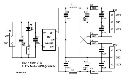
A standard USB cable is used to connect the probe power supply to the USB outlet on the oscilloscope; the type is unimportant, as even a charging cable is adequate. C1 and C2 filter the DC voltage from the USB port and LED1 indicates that the power is on. The heart of the circuit is the DC-DC converter type IH0512S from XP Power. It generates symmetrical ±12 V from +5 V with a maximum output current of ±84 mA, and it is galvanically isolated (with an electrical barrier between the input and output to improve safety)! The isolation voltage is 1,000 V, meaning there should be no ground problems when making measurements. The output voltage is filtered using various capacitors and ferrites, which can be omitted when working at the AD8479’s maximum measurement frequency of 130 kHz or replaced by 0-Ω resistors or wire straps.
To connect Rosenkränzer-type probes, I used 3.5-mm stereo jack sockets. These connectors are nice and compact, although they do have the disadvantage that their contacts are short-circuited momentarily when the jack plugs are inserted. In order to prevent damage, 100-Ω resistors are provided in each output circuit. Since the total current consumption of a probe is in the range of a few milliamperes (the AD8479 datasheet indicates about 850 µA; the only additional current drawn is by the operating voltage indicator LEDs D5 and D6), the voltage drop arising across these resistors is not a problem.
Read more: OSCILLOSCOPE DIFFERENTIAL PROBE USB POWER SUPPLY