
In this experiment I will use an Arduino and a DCF77 time signal radio receiver to measure the stability of an ovenized crystal oscillator running at 1 MHz. It demonstrates that 50ppb (or 50 milliHerz) can be achieved on the short term, whereby an aging effect of 0.1 ppb per day is demonstrated with a 18 month long dataset. The output of the 1MHz oscillator is fed into a 248 counter and six 74HC165 parallel in, serial out (piso) conversion ICs that are controlled by an ATMEGA 2560, the circuit is described here. With this setup running at 1 MHz you get a rollover every 10 years, the resolution is 1 microsecond. In principle you could do this also with an Arduino but I decided for this set-up since I already had most of the components left over from an earlier experiment.
With the 48 bit counter and compare the output to the time synchronization signal received from the DCF77 transmitter in Frankfurt Germany, about 450 km from Rotterdam in the Netherlands. Once you collect 720 data frames after 12 hours a regression can be made between the internal clock and the time standard. The slope of the regression curve results in the frequency offset relative to the nominal oscillator frequency. In fact, the oscillator runs currently at -27.40 +/- 0.05 Hz below the reference frequency, and it is mostly affected by temperature. For this reason the oscillator is kept in an oven at approximately 60 degrees, it comes with its own power supply and operational amplifiers that are separated from the digital part. I managed to get the annual frequency variation of 50 milliHerz (or 50 ppb) in this way.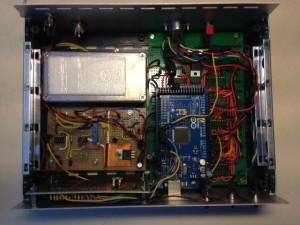
In the oven I soldered a transistor on the 1MHz crystal case (it survived the torture), the thermostat it continuous and the precision is as good as the NTC and the resistors are. There is Styrofoam on the inside of the aluminum box to provide some protection against heat losses which seem to occur during the winter. Maybe I should try a double thermostat at some point.The experiment assigns one microsecond counts originating from the TCXO to the one minute time frames received from the DCF time standard in Germany. This allows one to compute regression coefficients, after 12 hour they give me the frequency offset of the oscillator relative to the time standard. The frequency offset is continuously evaluated, after 12 hours an estimated value is stored in the EEPROM of an ATMEGA 2560 board that also displays in real time the received DCF data and the estimated frequency offsets. Every 6 weeks I read out the EEPROM, and that results in the following graph where the red line is a trend curve fitting the individual 12 hour measurements.
For more detail: Ovenized crystal oscillator frequency stability