
So this is the PALPi V4 which is a DIY Retro Game Console powered by a Raspberry Pi Zero W.
The IDEA here was to make a portable handheld gaming console that can run RETRO Games like Contra, Pokemon, Super Mario ETC.
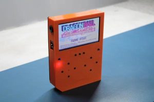
For Display, I've used a 4 inch Car Monitor Display which is controlled by Composit PAL output.
As for the emulation OS, I used RECALBOX as it comes with many preinstalled games.
In this Instructables, I'm gonna show you guys the whole built process for this Retro Game Console.
Supplies
Following are the things I used in this built-
- Custom PCB (which was provided by PCBWAY)
- IP5306 IC
- 10uf 1206 Package Capacitor x8
- 2R 0805 Package x1
- 1K 0603 Package x2
- 10uH Inductor x1
- SMD Button x1
- Indicator LEDs x4
- THT USB Micro Port x1
- Li-ion Cells 3.7V 2600mah
- Female Header pins Con40 x1 (or use two CON20 Pin)
- Toggle switch x13
- Raspberry Pi Model 3B+
- 4 inch PAL Display (salvaged from CAR MONITOR)
- 3D Printed Body
- DC Barrel Jack
- 5V Barrel Adaptor (for charging the Li-ion cell)
Step 1: Previous Edition
Previously, I made the PALPi V1 which had the same internal spec as this console but it was thick and uncomfortable to hold.
https://www.instructables.com/PALPi-Retro-Game-Console/
The PALPi Lite is an improved version that is now slimmer than the original V1 and is comfortable to hold.
Step 2: Getting Started
I started by first designing a slim box-shaped body in fusion360 along with a basic PCB Shape as a reference.
After finalizing the design, I exported the PCB's DWG file so I could import it into my PCB Suite to make the outline for the PCB and place the switch in its assigned place.
Step 3: RECALBOX
I used RECALBOX OS to run this setup.
Why Recalbox OS, why not Retro Pi or other OS?
well, the answer here is simple, recalbox is an easy-to-use OS that comes with a lot of Free games pre-installed.
Also, it's small and can run on low spec raspberry pi systems.
like in my case, I'm using a Rpi Model 3B+ which has 1GB ram.
it's not exactly a powerhouse but it can handle a few retro games without breaking a sweat.
Installing it is also very easy
- Download the Raspberry Pi imager.
- Select the right OS for your device, which would be RecalBox
- select your system which is Rpi Model 3B
- Raspberry pi imager will do your work of downloading and installing the RecalBox on the memory card.
After installing the RecalBox os, you need to plug your Raspberry pi setup with a Keyboard as the first boot always requires a keyboard.
After booting the whole setup, the RecalBox works like a normal emulator.
Step 4: PCB Design
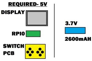
One of the hurdles during the designing process was how to power Raspberry Pi and Screen together with a 3.7V Source.
For that, I used a Power management IC which was IP5306.
It's a boost converter IC with a bunch of features that includes Low and high cut of the cell during overcharge and over-discharge along with a battery fuel indicator.
It can output 5V 2A which is enough for our setup.
I took its minimal setup from its datasheet and prepared a board that has switches along with the power management ic setup that boosts the Li-ion cell to power the Raspberry pi and display.
After finalizing the schematic, I converted the schematic into PCB File and started the layout by first placing the switches in their place by using the earlier PCB Outline as a reference.
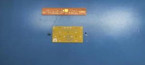
Step 5: Getting PCBs From PCBWAY
I used PCBWAY PCB Service for this project. I first uploaded the Gerber file of this project on PCBWAY's quote page.
I choose yellow soldermask with white silkscreen, there was no special reason for choosing yellow soldermask, I just wanted to see the yellow PCB.
I received the PCBs in a week and the PCB quality was pretty great, This PCB is small and I like how the quality of these PCBs was not compromised because of quantity or size.
PCBWAY, you guys rock.
Check out PCBWAY service for great PCB service at less cost!
Step 6: ASSEMBLY
The Assembly process of the Board includes mainly three steps
- Solder paste dispensing process
- Pick & Place process
- hotplate reflow
- Testing
- Adding Through-hole componenets
Step 7: Solder Paste Dispensing Process
Now the first step is to add solder paste to each components pad one by one.
To Apply solder paste, I'm using a Solderpaste Dispensing Needle with a Wide syringe, and the solder paste I'm using is a regular solder paste consisting of 63% Tin 37% Lead.
Step 8: Pick & Place Process
After applying Solderpaste we move on to the next step which is to add componenets to their assigned location.
I used an ESD Tweezer to place each component in its place.
Step 9: Hotplate Reflow Soldering Process
After the “Pick & Place Process”, I carefully lifted the whole circuit board and place it on my DIY SMT Hotplate.
the hotplate heats the PCB from below up to the solder paste melting temp, as soon as the PCB reaches that temp, solder paste melts and all the components get soldered to their pads, we lift the PCB and then place it on a cooler surface for a little bit, to cool down the heat of PCB.
Step 10: TESTING THE BOARD (A)
After reflow, the PCB is partially completed. we first need to test whether the IP5306 setup is working or not.
To check that I added wires to the INPUT and battery side.
I then connected the input side with a USB micro breakout and battery side with a 3.7V Li-ion cell on a breadboard.
Step 11: TESTING THE BOARD (B)
we then turn ON the IP5306 setup by pressing the SMD button on PCB, doing this will kickstart the circuit, and the LED fuel gauge will display the battery percentage.
we then measure the voltage across the output of the IP5306 setup which should be 5V.
At last, we connect a 5V 2A Charger via USB micro port (this is for charging the battery), Indicator LEDs will start to blink in a sequence that shows how much battery has been charged.
After checking the above points, our circuit is working and now we can move on to the next step which is to add the remaining THT Componenets
Step 12: ADDING THT COMPONENTS
THT componenets include 20 Pin header pin connector x 2 and 13 tactile switches.
Step 13: First Boot
Before moving onto the main assembly, we first need to boot the Rpi for the first time.
At this moment, it doesn't have the PAL port enabled or GPIO buttons enabled.
To enable them, we first connect the Pi with an HDMI cable and a keyboard along with a 5V 2A stable power source (smartphone adaptor).
We boot up the Recalbox and head over to network settings for enabling the WIFI.
Editing Part of Config file
- Open Win SCP on your computer, enter the raspberry pi IP Address on it, the user name will be root, and the password for the pi is recalboxroot.
- go to recalbox>share>system>recalbox.conf
- For Enabling GPIO Buttons, we only need to change two things in the below section.
set controller.gpio.enabled = 1 (It was 0 before) and change controller.gpio.args.map=1, 2 to controller.gpio.args.map=1 (2 is second player controlls)
- Just change your default setting according to mine, then reboot the whole setup, and BANG, our Recalbox setup will work with buttons.
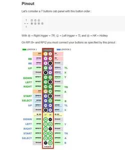
Also, I've attached a GPIO Map for the buttons. The switch connects each GPIO with GND and that's how the RPI registers the button Tap.
Step 14: Main Assembly
- The main assembly includes adding the circuit board to the 3D Printed body first.
- then we add the PAL Output of raspberry pi to the main circuit and place the Pi on the circuit board.
- then we add the screen to the main body and connect its PAL port to the PAL port of raspberry pi, VCC to VCC, and GND to GND.
- At last, we add hot glue to hold the screen in its place.
- I then connected an external tactile switch in parallel to the SMD button, this tactile switch is for turning ON or OFF the game console's main power source. I solder the tactile switch on a perf board.
- then we add Li-ion cell to the battery side of the circuit.
Step 15: FINAL ASSEMBLY
- To complete this setup, I added a barrel dc jack to the input side so I could charge this device with a 5V Charger.
- I used hot glue to hold the barrel jack and Li-ion Cell in their place.
- Then I glued the Tactile switch to one side of the 3D Printed body.
- At last, I added the bottom lid to the body with four M2 Screws and our Retro Game console is ready to rock and roll.
Step 16: RESULT
Here's the result of this built, a complete handheld gaming console that can run pretty much any old game, from PS1 to the atari game console.
Step 17: What About Sound?
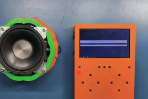
This console doesn't have a speaker setup built-in that outputs audio BUT, we are using Raspberry Pi Zero W which has BT and WIFI onboard which means we can connect any BT Speaker with it and play games in their original audio.
- To do that, we go to Setting menu > Bt controller and add a new Bt device.
- pair it up and the Bt system will get active.
As for the sound, I'm using my previously made Jack O lantern Bt speaker that you can check out from here.
Step 18: ADDING GAMES ON IT
this is an Opensource retro game emulator, which means we can add any old game from any game system and run them on this setup!
we first need to download the custom ROM of any game you want to play on this game console. For example, I downloaded pokemon emerald. then we first need to connect the Recalbox to our WIFI router.
- We open WinSCP and add our Recalbox IP Address on it along with the user name- root, and the password for the pi is recalboxroot.
- go to this menu recalbox>share>rom, it contains all the emulator's folder which contains games ROM, I wanted to add pokemon Emeral in it which runs on Gameboy advance so I had to copy-paste its ROM file in the GBA folder.
- now reboot your raspberry pi setup and open the GBA Emulator menu, and you will see the newly added game.
Step 19: CONCLUSION
This setup works and it's 100% Practical in the real world. I played more than 10 hours on this thing in a couple of days.
One issue that I found out was the battery capacity was not enough so I added one more 2600mAh Cell in parallel with the existing Cell. This increased its backup time.
Also, Raspberry Pi Zero, in general, is not powerful enough to run PS1 games which is a bummer, one option is to overclock the CPU and add a heatsink on it to counter the heating problem.
A more permanent solution would be to change it with New Raspberry Pi Zero W2 or get a Raspberry Pi 4 with more RAM.
Originally I wanted to go with compute module but because of its unavailability, I was unable to get one.
Source: PALPi Lite Edition