
Hey, Guys what's up?
So this is PALPi which is a Raspberry Pi Zero W Based Handheld Retro Game Console that can run pretty much every retro game, from SNES to PS1.
The brain of this project is the RECALBOX OS, an Opensource Game Console OS based on Retro Arch.
Raspberry Pi Zero W is being used here with a custom PCB that has SMD Buttons on the front side and a battery on the back.
This is currently the Fifth Iteration of the PALPi Game Console System.
Its previous version was great but it had a battery issue, there wasn't much space inside the 3D Printed body and by increasing the thickness we could accommodate more cells but it would also increase its size.
This version is also thick as it consists of two boards stacked together, we can add cells and everything later in a single board, this needs further refinement in this case but for now, it's working and the SMD Buttons feel a lot better than previously used tactile buttons.
Supplies
following are the stuff used in this built-
- Custom PCB (which was provided by PCBWAY)
- IP5306 IC
- 10uf 1206 Package Capacitor x8
- 2R 1206 Package x1
- 1K 0603 Package x2
- 10uH Inductor x1
- SMD Button four pin x 10
- SMD Button two pin x 3
- Indicator LEDs x4
- Type C USB Port x1
- Dual 18650 cell SMD Holder
- Li-ion Cells 3.7V 2600mah x2
- Female Header pins Con40 SMD Version
- Raspberry Pi Zero
- 4-inch PAL Display (salvaged from CAR MONITOR)
- 3D Printed parts
Step 1: 3D Design
This Version is a special one, instead of 3D Printing the whole body, PCBs have been used for the overall construction.
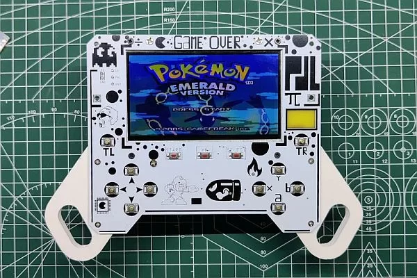
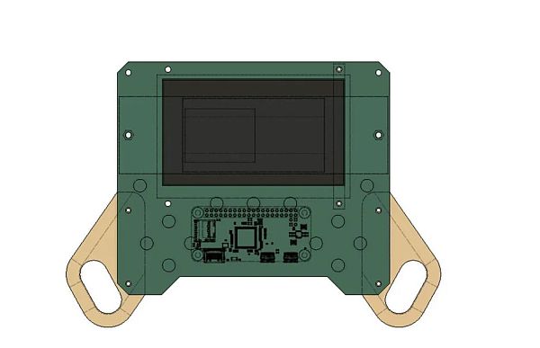
Front Panel Has SMD Buttons on TOP Side and Raspberry Pi on BOTTOM Side, Screen is also attached to the front Panel through two screen holders from the BOTTOM side of the board.
It also holds two 3D Printed Hand Grips that increase its size and enhance the holding experience significantly.
As for the Power, there's a second PCB dedicated to Cells and their charge management circuitry.
The Battery Holder PCB is connected to the Front Panel through three 25mm Long PCB Standoffs.
I used fusion360 to make this design, there are a total of four parts that we need to 3D Print which are the Controller Grip which consists of left and right pairs, the second part is the screen holder we need to print 2 units.
As for print settings, I have used a 0.4mm Nozzle at 0.2mm layer height and 25% infill.
Step 2: Schematic
This Project utilizes two separate boards so there are a total of two schematics used in this project.
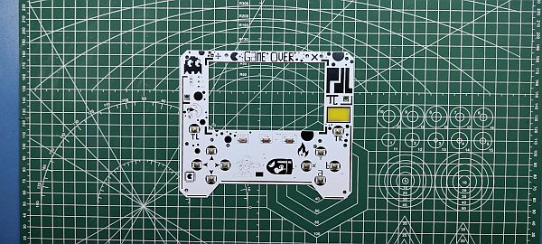
“Front Panel PCB” as its name suggests is the front part of the console, It holds the screen in its place and has 13 SMD Buttons.
It also contains the Raspberry Pi Header Pin socket which is mounted on the bottom side of the board.
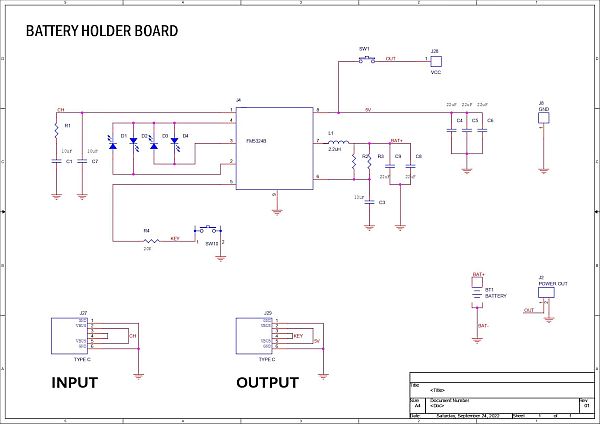
“BatteryHolder PCB” is the second board that holds the main power source of this whole device, two Li-ion cells.
IP5306 setup is used, for charging, there's a USB Type C Port and also one for discharging.
Step 3: PCB Design
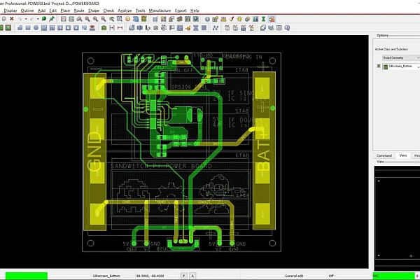
After getting the rough Idea of the shape for both the Front and back PCB, I designed two separate boards, Front Panel, and Battery Holder PCB.
The Front Panel PCB contains mainly the screen and buttons, it has mounting holes for adding the Battery Holder PCB and Screen holder.
The Battery Holder PCB was simple as well, it's an IP5306 Based board that controls Li-ion Charge and discharge cycle as well as gives stable 5V output for Raspberry Pi and screen to power.
Both PCBs are made in such a way that they can be connected by three PCB Standoffs making the PCBs the main body so we don't have to use any sort of 3D Printed cover for this version.
Step 4: PCBWAY
After completing both designs, I exported their Gerber data and sent it to PCBWAY for samples.
A White solder mask and Black silkscreen were used for this project.
I received PCBs in a week and the PCBs were nice as expected.
I like the quality of the white solder mask, it was a tough sample to manufacture as the silkscreen that I have laid out on this board was not completely symmetrical and I also added a rectangular void in the middle region which was not like normal PCB layout but PCBWAY did an excellent job of manufacturing this PCB with no error whatsoever.
check out PCBWay service for getting great PCB service at less cost.
Step 5: Solder paste Dispensing Process
Now the first step is to add solder paste to each component pad one by one.
To Apply solder paste, I'm using a Solderpaste Dispensing Needle with a Wide syringe, and the solder paste I'm using is a regular solder paste consisting of 63% Tin and 37% Lead.
We first applied solder paste to the Battery board and then did the same for the front PCB.
Step 6: Pick and Place Process
After applying Solderpaste we move on to the next step which is to add components to their assigned location.
I used an ESD Tweezer to place all the components on both the Front and Battery PCB.
Step 7: Hotplate Reflow Process
After the “Pick & Place Process”, I carefully lifted the whole circuit board and placed it on my DIY SMT Hotplate.
the hotplate heats the PCB from below up to the solder paste melting temp, as soon as the PCB reaches that temp, the solder paste melts and all the components get soldered to their pads, we lift the PCB and then place it on a much cooler surface for a little bit, to cool down the heat of PCB.
Step 8: Adding SMD Rpi GPIO Header and CON2
- Next, we add the 40 Pin Female Header Pin on the Front Board's bottom layer using a soldering iron, this will take a while as we have to manually solder each pin to its SMD Pad.
- After adding Header Pin, we add CON2 JST Connector to the 5V and GND pin of the board, we later connect a JST Wire Harness to this CON2 for powering the RPI with Battery Board.
Step 9: SMD Li-ion Cell Holder
Next, on the Battery Holder PCB, we add Li-ion Cell 18650 SMD Holder in its place by using a regular Soldering Iron.
Step 10: Battery Board Test
- After adding the SMD Cell Holder, we add two 3.7V 2900mAh Li-ion cells in the Cell Holder, making sure to place them in the right polarity.
- Next, we press the Main ON OFF Button and measure the voltage at Output Terminals which should be more than 5V.
Step 11: Adding Screen With Front PCB
- We now add the PAL Screen on the Front Panel by using two 3D Printed Screen holders and a couple of screws.
- After this, we connect the Screen's VCC to 5V of the Front Panel board, GND to GND, and PAL port to PAL port connector given on the left side of the board.
Step 12: Adding Side Holder/Grip With Front PCB
Next, we add two Hand Grips to the Front Panel, these grips are 3D Printed and are mounted by two M2 screws each.
Step 13: Raspberry Pi Zero Merge With Front PCB
It's time to place the Raspberry Pi Zero in its Header socket.
- We first solder a wire to the PAL port nearby the Raspberry Pi zero area.
- Next, we secure Raspberry Pi in its place and add solder wire to the PAL port of the Raspberry Pi so we can attach the wire easily to it.
Step 14: Front PCB and Battery Holder PCB Merger
- We now start the final assembly by first adding Three PCB Standoffs to the Battery Holder PCB.
- Next, we place the Battery Holder PCB on the Bottom side of the Front Panel and use three M3 Screws to connect both PCBs.
Step 15: Connecting Battery Board With Front Panel Through JST Wire Harness
At last, we add a JST wire harness to the Positive and Negative ports of the Battery Holder PCB so we can connect this wire harness with the CON2 JST connector on the Front Panel.
Read more: PALPi V5 Handheld Retro Game Console