
Hey Everyone what's up, So here's something cool.
This is PALPi Version 2 which is a Huge Retro Game Emulator system with a 7-inch display and custom PCB!
Recently, I got a Raspberry Pi IPS Touch 7-inch Display from the PCBway gift shop and I thought “Hey, let's make a huge Handheld game system that works even better than my previous setup”
In this post I will show you guys how I made a Huge Retro Game Console by using the 7 inch IPS Display, recalbox OS and a custom board from my previous Game Console built so without wasting any more time, let's get started
Supplies
- 7 inch IPS Display (which was provided by PCBWAY)
- Raspberry Pi Model 3B (any model can work, even zero but it's better if we use Model 3B+ or higher models with more RAM)
- Custom PCB
- IP5306 IC
- 10uf 0805 Capacitors
- USB Port USB
- Micro Port
- Li-ion Battery with CON2 Connector wire (JST Connector)
- CON2 Connector
- 10k 0603 Resistance
- 2R 0805 Resistance
- Vertical Push Button
- Regular Pushbuttons
- RPI GPIO Ribbon cable
- HDMI Cable (small length cable)
- USB Cable
- 5V 2A Charger
- Keyboard
- 3D Printed parts for Display's Frame
Step 1: Prologue
a few months ago, I made this PALPi setup which was a Rpi Zero-based Retro game emulator which uses Recalbox OS as an emulation system.
It was a great project but it had soo many flaws, It uses a Composite PAL display which was small and not exactly great.
Also, it had no sound but the main problem was that it wasn't very powerful as it uses an RPI Zero and sometimes the game freezes or setup turns itself OFF.
I tried adding some cooling setup and even overclocking the RPI Zero but the freezing problem was still there so I removed the RPI zero from the equation entirely.
For Preparing the V2 of the PALPi project, I got myself a huge 7 inch IPS display that uses a much better video output method, the mighty HDMI.
Also, I used the same PCB setup for this project from the previous one.
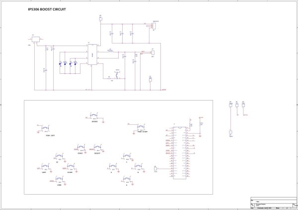
This Board is based around IP5306 which is a power management IC that boosts a 3.7V Li-ion cell to 5V 2A for Raspberry Pi and Display to work.
However this PCB was designed for the BOX shaped game controller project and the one I'm making right now is more like a console so for now I will be using this board but in the next iteration, I will be making a custom board shaped like a console D PADs and ABXY Pads.
Step 2: About the Display
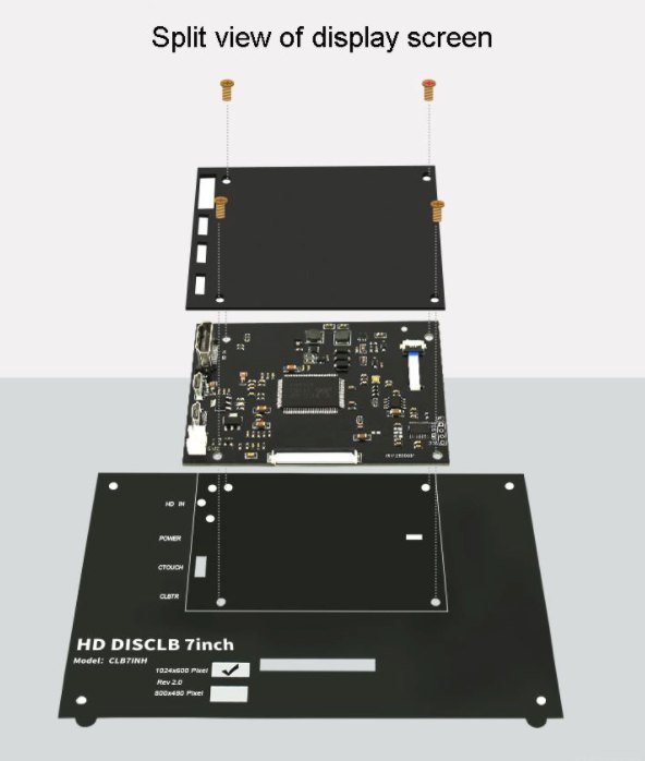
Display size: 7 inch
Resolution: 1024*600px
Principle: touch control
Interface: USB/HDMI/ power interface
Suitable for: Raspberry Pi/NVIDIA /Windows
Weight: close to 265g
Support: Raspberry Pi, NVIDIA, Ubuntu mirror, computer secondary screen
The unboxing of this display was also pretty straightforward, it comes in a decent cardboard box with a bunch of stuff along with it like a stand, HDMI to Micro HDMI cable.
Step 3: Display 3D Printed Frame
Now before doing anything, this display is not exactly robust so I first modeled its body in Fusion360 and then 3D Printed all the parts on my ender 3 with white PLA.
The infill of parts was at 50% and no supports were required.
I made the body for this display like a Frame instead of making a BOX Body.
Step 4:
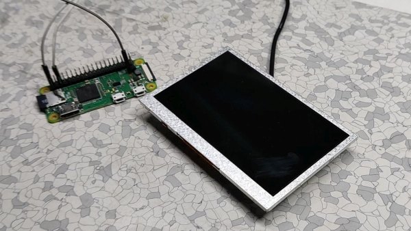
Then I assembled the whole display and then added Raspberry Pi Model 3B+ on the backside of the display with given mounting holes.
I had to enlarge the holes on the raspberry pi from 2.5mm to 4mm.
After assembly, we now have a cool-looking RPI setup with a proper robust body.
As for Display wiring, I connected the HDMI out of Rpi to the HDMI port of the display with a small HDMI cable that came along with the display.
now let's move on to the next crucial step which is “How to power this setup”
Step 5: POWERING THIS SETUP
Now to power this display, we have two options here, to use a 5V Charger as a power source or use a dedicated Battery source.
To power RPI, I used a 5V wall adaptor and for display, I used a powerbank setup. this method does work but the issue with this setup is the portability problem.
this setup is powered by a wall adaptor which is not at all portable.
Step 6: Using recalbox
As for the Game Console OS, I am using RecalBox OS here.
Why Recalbox OS, why not Retro Pi or other OS?
well, the answer here is simple, recalbox is an easy-to-use OS that comes with a lot of Free games pre-installed. Also, it's small and can run on low spec raspberry pi systems.
like in my case, I'm using a Rpi Model 3B+ which has 1GB ram. it's not exactly the beast but it can handle a few retro games without breaking a sweat. probably.
Installing it is also very easy
- Download the Raspberry Pi imager.
- Select the right OS for your device, which would be RecalBox
- select your system which is Rpi Model 3B
- Raspberry pi imager will do your work of downloading and installing the RecalBox on the memory card.
After installing the RecalBox os, you need to plug your Raspberry pi setup with a Keyboard. After booting the whole setup, our RecalBox works like a normal emulator.
By using a keyboard, we can play a bunch of games like I'm playing this old retro game called URANUS ZERO which is running on GBA or we can run DOOM on this device which is also awesome.
Step 7: Portable Setup

Using a 5V charger is good but what if I want to make a handheld game console setup with this display.
I have already prepared a similar board for my previous game console project that utilizes a power management IC which is this IP5306 to step up the Lithium-ion battery voltage from 3.7V to 5V 2A.
It also contains the switches for the controller part.
Step 8: Schematic
https://www.instructables.com/PALPi-Retro-Game-Con…
Check out the previous post for more details but basically, I first prepared a breadboard edition and after finalizing it and testing it thoroughly, I prepared this PCB and sent it to PCBWay for samples.
Step 9: Getting PCBs From PCBWay
I uploaded its Gerber data to PCBWay's PCB Quote Page and ordered 5 PCBs in the Black solder mask.
I received PCBs in a week which was fast and I have to say, PCBs that I received was great as expected!
Buying display from PCBWay Giftshop
Also, I purchase the display for this project from PCBway's gift shop.
https://www.pcbway.com/project/gifts_detail/Raspb…
It's a nice marketplace from where we can get a bunch of stuff with beans. Beans are kinda like reward points that are earned by ordering PCBs from PCBway or by posting projects in the PCBWAY community.
Check out PCBWAY's giftshop for getting cool stuff for a very less price.
Step 10: PCB Assembly
The Assembly process of this includes mainly three steps
- solder paste dispensing process
- pick & place process
- hotplate reflow
- Adding THT components
Step 11: Testing and Final Wiring
After finalizing the PCB, We plug in the battery and measure the voltage across the battery which is around 3.9V, and on the output side, the voltage is 5V which is suitable for running both raspberry pi and display.
oh also, I've added a USB cable to 5V and GND so I could plug this in display and power it. the raspberry pi will get powered by the GPIO headers directly so we don't have to use its onboard USB port I plug in the header pins of the custom Circuit with Gpio pins of Rpi with a ribbon cable.
this setup is temporary as I will be making a proper Gameboy layout PCB later for the next version.
Step 12:
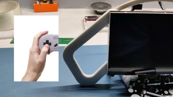
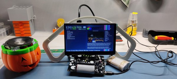
here's how this setup would look for now. it's very makeshift and yes it's not proper or portable at all as it still has so much stuff just hanging around.
This setup is just for proving a concept, in the next version I will make three boards, one for the battery and power management, and two for switches.
Anyways, let's move on to the next step which is to enable the Game controller Via the GPIO option in the recalbox config file.
Step 13: Editing Part of Config File
- Open Win SCP on your computer, enter the raspberry pi IP Address on it, the user name will be root, and the password for the pi is recalboxroot.
- go to recalbox>share>system>recalbox.conf
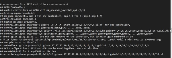
- For Enabling GPIO Buttons, we only need to change two things in the below section.
set controller.gpio.enabled = 1 (It was 0 before) and change controller.gpio.args.map=1, 2 to controller.gpio.args.map=1 (2 is second player controlls)
- Just change your default setting according to mine, then reboot the whole setup, and BANG, our Recalbox setup will work with buttons.
Also, the GPIO Map for the buttons is attached above. The switch connects each GPIO with GND and that's how the RPI registers the button Tap.
Step 14: Games
Recalbox has so many inbuilt games from many different game stations.
My favorite of these inbuilt games is the original DOOM which is a fun game to play.
Also, this is an Opensource retro game emulator, which means we can add any old game from any game system and run them on this setup!
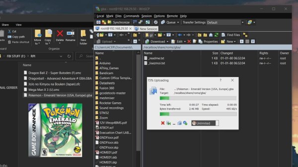
we first need to download the custom ROM of any game you want to play on this game console. For example, I downloaded pokemon emerald. then we first need to connect the Recalbox to our WIFI router.
- go to this menu recalbox>share>rom, it contains all the ROM Folder, I wanted to add pokemon Emeral in it which runs on Gameboy advance so I had to copy-paste its ROM file in the GBA folder.
- now reboot your raspberry pi setup and open the GBA Emulator menu, and you will see the newly added game.
Step 15: Adding BT Speaker for Sound
Also, this setup does support audio functionality but I haven't enabled it or added any amplifier setup for the external speaker.
Good thing is, we are using a Rpi 3+ which comes with BT so we can pair any external speaker to this setup.
Go to Setting menu > Bt controller and add a new Bt device.
pair it and the Bt system will get active.
Source: PALPi Version 2, Big Edition