Project overview
The project aims to equip standard remote control (RC) car with improved control. Commonly used RC car control joystick is replaced with PC racing set. This improvement ensures more precise driving and exceptional user experience. Moreover camera attached to car enables view from perspective of RC car, e.g, what would a driver in RC car see. User then can watch real time video on PC screen. Two servos enables camera to turn and therefore driver can observe surrounding of the car. Let's see now how it works. Driver controls car with steering wheel and pedals. He can drive out of his field of view, for example behind the corner or to different room because of the camera is streaming on the users screen. Therefore RC car can also be used for scouting.
Project Team
Project was assigned to a team of 5 people of three different study backgrounds.
Team members and study backgrounds: Jussi Taskinen – electrical engineering, Klaus Kivekäs- mechanical engineering, Tomáš Lazák – mechanical engineering, Pravin Luthada – mechanical engineering, Kääriäinen Lassi – automation and systems technology.
Technical description
Block diagram of the system is presented below.
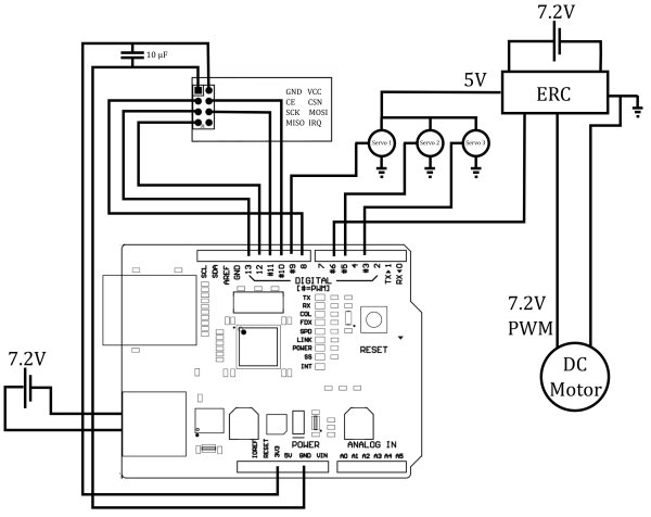
Position data was attained by reading potentiometers attached to the racing set with Arduino Uno. An additional Arduino Uno placed on the RC Car. Nordic semiconductor NRF24L01 2.4 GHz radio transceivers were connected to both Arduinos and used to broadcast and read control data. The signals read by on-board Arduino were then used to control actuators on the RC car (three servos and one DC motor). Raspberry Pi in addition to its wifi and camera modules were also mounted on-board the car. Raspberry pi was used to stream the video through wifi to PC next to the racing set for video guided driving.
Mechanical components
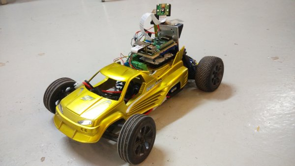
For the RC car we used an existing model, LRP's S10 Twister Buggy. The rear-wheel drive buggy uses a dc motor for controlling acceleration and deceleration and a servo for controlling the turning of the front tires. We fitted the chassis with a different body because the original body was not suitable for accommodating all the required electronics on the car. The wheel and pedal set used was an old Thrustmaster set from the 1990s. The steering wheel and pedals used potentiometers for position sensing, although, we had to replace the potentiometers in the steering wheel and gas pedal because the old ones had become imprecise.
The vertical and horizontal orientation of the camera was controlled by two servos. The servos were controlled by two potentiometers which were attached to the base of the steering wheel. We attached a steel plate at the rear of the car for attaching the Raspberry Pi and the camera with its servos. The Arduino was attached onto the yellow body of the car. The Raspberry Pi was attached to another steel plate with a wooden plate on top of it. For attaching the servos to the steel plate and for attaching the camera to the servos we 3d-printed some parts which were designed using Creo. The camera assembly with the 3d-printed parts, servos and the camera is shown in the image below.
Two holes were drilled to the wheel module to accomodate servo turning knobs.
Electrical components
The position data of pedals and wheels was determined by potentiometers. We replaced some worn potentiometers with new ones. Both pedals are read by a potentiometer as well as the wheel. Two potentiometers were attached to the wheel module as servo turning knobs. Potentiometers were read by Arduino Uno (ATmega328 microcontroller). Nordic Semiconductor NRF24L01 was used to broadcast the data. Radio operates at 2.4 GHz. Arduino powered via USB cable from PC.
The car was equipped with 1 x Arduino Uno with NRF24L01 radio module connected. All servomotors were directly connected to Arduino, and pulse width modulation was sent to electronic speed controller which controlled the DC motor. Motors were connected via speed controller to a larger 3300 mAh 7.2 V (check values) battery and Arduino was powered via power plug by 1600 mAh (check value) battery. To reduce number of wires, a PCB was made (image of PCB does no longer indicate the correct connection order because Arduino is no longer powered from Vin port).
Raspberry Pi was used to stream the video. Camera module and wifi module were connected to Raspberry Pi. It was powered by a designated battery.
Software
Arduino:
The coding and uploading was done by using the Arduino development environment. The transmitter Arduino is responsible for reading the potentiometers, scaling and manipulating the control values and sending them to the receiver Arduino. The transmitter Arduino's code starts by including the libraries and declaring the analog read pins for the potentiometers. Both Arduinos are using a third party library called RadioHead. The communication between an Arduino and a NRF24L01 is implememented by using SPI-protocol, therefore SPI library is also needed. In the transmitter Arduino's setup-function radio communication is initialized. It sets the cahnnel, data sending rate and transmit power. The loop-function is executed repeatedly after the execution of the setup-function.
The receiver Arduino is used to write pulse width modulated signal to the servos and the DC motor's speed controller. The receiver Arduino's code starts by declaring variables and by including libaries. In addition to the SPI and the RadioHead library, the Servo library is also included. It's used for writing pwm signal. In the setup-function servo variables are connected to pins and radio communication is initalized. In the loop-function the control values are received by using nrf24.recv-function. The received values are then used to write pwm to the actuators. Pwm signal is generated by using Servo library's write-function.
For more detail: PC racing set controlled RC car with video streaming


