
This instructable will allow you to use your PiFace to control 8 LEDs in a chasing flashing pattern. This will help you get to grips with basic use of python to control the PiFace as well a basic electronics, I'm writing this up in full to help combat the complete lack of documentation for the PiFace.
For this Project you will need:
8 x LED's (Any Colour or Size)
1 x Resistor (Value to be worked out in Step 1)
1 x Breadboard
Selection of Jumper Wires
(Instead of the Breadboard and Jumper Wires you can solder the entire thing together, however I would fully recommend a breadboard as this will make things much much easier)
Step 1: Calculating Resistor Values
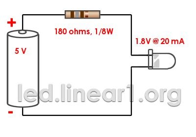
If you simply attach your LEDs directly to the outputs on your PiFace you are likely to burn them out straight away so the first thing we need to do is to calculate the value of the resistor you will require in your circuit. The resistor will increase the resistance in the circuit before the LED and stop the entire current reaching the LED.
In my case I am using some 3mm LED's that I have lying around, the important things we need to know are
Power Supply Voltage (V) – 5V (This is the power provided by the Pi)
Diode Forward Voltage (V) – 1.8 (The Voltage of the LED, this should be written on the packaging they came in)
Diode Forward Current (mA) – 20 (The Current of the LED, this should be written on the packaging they came in)
(The two values in bold are values you must provide, the ones given here are for LED's I am using)
The easiest way to work out the resistor that you require is to use an online resistor calculator. In my case the calculator suggests that I use a 180 ohm resistor, you can get away with using a resistor with a greater value but I won't recommend using one with a lower value.
Step 2: A Quick Breadboard Explanation
Using a breadboard is a great way to quickly/temporarily build a circuit without having solder anything. Each of the groups of holes can be thought of as wires and each hole as a soldering point on the wire. All component connections need to go from one group of holes to another just as you would solder each component from one wire to another.
On a normal breadboard you will have two columns of holes usually meant for positive and negative connections to the power source, these are the only holes on the board that are connected vertically, the rest of the holes are connected in rows with a gap in the middle, the rows ARE NOT connected across this gap.
In the diagram of a breadboard above you can see that I've drawn boxes around two columns of pins that are all connected together and two rows of pins.
In the second image you can see a simple single LED breadboard circuit, assume the red collum is connected to the positive terminal on a batter and the green to a negative. You can see the LED has one terminal in one row and another terminal in a second row, this LED is connecting the two rows together. The the two rows are then connected to the negative and positive columns completing the circuit.
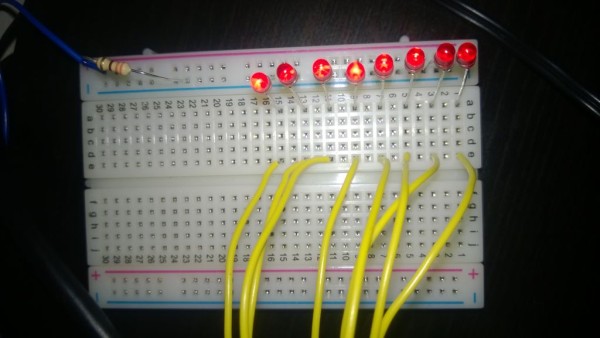
Step 3: Wiring up the Breadboard
BEFORE CONNECTING ANYTHING TO THE PIFACE I RECOMMEND TURNING IT OFF.
For more detail: PiFace LED Chasing Lights Raspberry Pi