
The Poor Man's bi-ped Robot – using RP2040 and Micropython project consists of three instructables:
- Poor man's bi-pedRobot Hardware describes how to build the robot hardware and documents the electronics to run the servos which move the robot.
- Poor man's bi-ped Robot Controller(this instructable) describes the software which is running on the robot electronics to make the robot walk.
- Poor man's Robot Remote Control describes the User interface to program the robot to walk a certain distance and control the parameters, which influence the way the robot walks. (to be published soon)
This Poor man's bi-ped Robot Controller instructable describes how to control a bi-ped robot, explains basic concepts such as how to control servos using RP2040 PIO programs, a bit of inverse kinematics, walking pattern generation and the software modules needed to make Robi the robot walk.
To implement the robot controller at least some basic Python programming experience is needed. The matter is a bit complex and in case the hardware and/or software is not working as expected, some understanding of the code is needed to understand and resolve the issue.
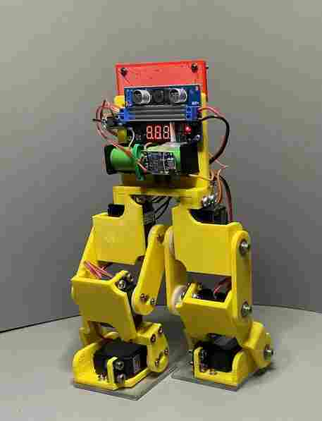
Robi is built with a WLan capable RP2040 based board to enable a “Robot Remote Control”. On Robi's side a small Web server provides a simple API to control the robot via WLan. With this API you can remotely program Robi to walk a certain distance and set parameters, which influence the way the robot takes steps. The UI sends status information received from Robi.
The instructable documents the project to make it easy to reproduce, but will not go deeply into all the knowledge areas, which are involved in controlling a bi-ped robot. Basic knowledge will be provided and I will provide links to resources, which I found very helpful.
The software provided is a starting point and by no means is a complete robot controller, it is shared with the hope to be a helpful resource for your robot projects.
Remarks:
- all modules with the headline starting with “Basics: ” in the Steps below are generic, and the software is implemented independent of the hardware implementation for Robi, so they can be re-used or adapted easily for other projects. The software modules are attached to the individual Steps.
- This instructable will provide a test software to test-walk Robi. To use the test software a long (e.g. >=1.5m) USB cable is needed.
Have fun reading on – and if you have questions or improvement ideas – feel free to add a comment below.
Supplies
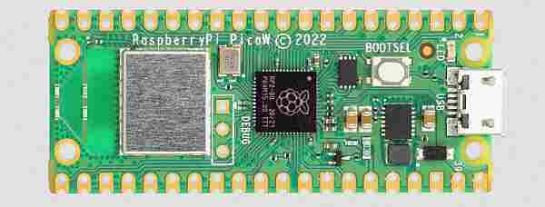
The hardware needed is a RP2040 based micro-controller board with WLan. I am using the RP2040 PicoW board. Add Micropython version 1.19.1 or higher.
If you have built the robot hardware of the “Poor Man's Bi-ped Robot Hardware – Using RP2040 and Micropython” instructable, the instructions and software below will work out of the box.
If you want to build your own bi-ped robot, continue reading. Likely many of the concepts (e.g. the inverse kinematics) and modules (e.g. the PIO programs on the RP2040) can be used as is. Feel free to adapt the modules to your needs.
If you ended up here being curious on how to control a bi-ped robot, read on!
Step 1: Basics: PWM Servo Control Using RP2040 PIO
Servo Control:
The concept of PWM servo control is explained in attached picture. The cycle time of a standard RC type servo is 20ms. The position of the servo arm (0 degree to 90 degree) is determined by the high time pulse width pw. Typically 0 degree corresponds to a pw of 1ms and 90 degree corresponds to a pw of 2ms. If you use servos with different specifications, see explanation in attached picture to re-calculate for your servos' specifications.
PWM Generation:
The RP2040 micro-controller has a very nice feature: the PIO.
With reference to the PIO PWM example in the RP2040 datasheet (section 3.6.8 PWM) the attached micropython module was developed. For Robi the PIOPWM class is used to instantiate six state machines to control Robi's six servos.
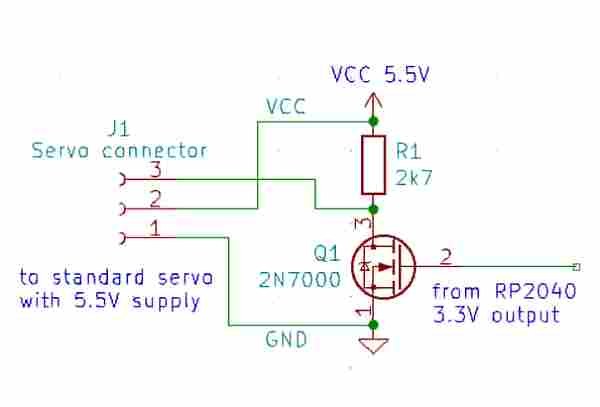
The Robi hardware uses simple FET level shifters to boost the 0V to 3.3V output of the rp2040 to the 0V to 5V input for the servos. These level shifters invert the signal, thus the PWM signal is generated inverted (see pictures).
Attached the PIO PWM micropython module for the RP2040 micro-controller with FET level shifters.
Step 2: Basics: Inverse Kinematics
I use inverse kinematics (IK) to calculate angles for hip, knee and ankle. For verification Geogebra classic is used. If you are interesting in more details or want to use IK for your own robot, I recommend following reading:
Oscar Liang: Inverse kinematics basics tutorial . This article goes beyond what I have implemented and beyond the capabilities of the chosen robot hardware, but the basics described in that article are helpful for any bi-ped robot project.
Geogebra classic can be found on the Geogebra Website.
For inverse Kinematics the robot hardware properties need to be known. These are upper leg length (thigh), lower leg length (shank) and height of the hip over ground. These properties are defined in the module robi_def.py as leg1, leg2 and height, described in more detail in Step 3.
Inverse Kinematics calculation for Robi can be found in the picture attached. Calculations are done in module calc_angle.py
I did set following conditions for the calculation to limit the degrees of freedom:
- the foot of the moving leg is always parallel to the ground
- the center of mass (CoM) is moving with the moving leg
- the moving leg is lifted straight up before moving forward to avoid collision with obstacles on the ground
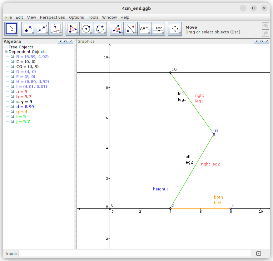
To show how Robi walks in principle, three example pictures are attached for a 4cm step, starting with the left leg moving. I simulated with Geogebra classic.
- 4cm_half_step: the right leg is supporting (on the ground), the left leg is lifted by step height (1.26cm) and half way forward (2cm). Robi's Center of Mass (point CG) has as well moved 2cm forward.
- 4cm_step: the right leg is still on the ground and the left leg has reached the full step and is on the ground as well. Next the right leg moves in a similar way, while the left leg is in support.
- 4cm_end: both legs have reached the 4cm step target and are in support on the ground. This is the starting position for the next step.
For each of these example positions of each leg – actually for much more positions in-between – the function target_angle() in module calc_angle.py is called to calculate the angles for hip, knee, ankle and hip_1. The auxiliary angle hip_1 is needed, because we move the CoM together with the moving leg (refer to angles a1 and h1 in first picture).
Step 3: Basics: Robot Properties
We need to describe our robot's properties. These are specific to the robot hardware and are kept in one place. All modules access them and use the same properties. As another benefit, if you change your robot hardware, e.g. servos or leg length, the change is maintained in one place. For Robi this place is in the module robi_def.py. This module contains comments to explain the properties in more detail.
The module contains:
- constants to instantiate the PIO PWM state machines. These constants are dependent on the servo specifications. For Robi the values are for standard servos with 20ms cycle time and 1ms to 2ms pulse width.
- constants for the mechanics: leg1 and leg2 length, the maximum CoM height (standing straight on both legs), the minimum CoM height (limited by the mechanics) and a safety height for initial lifting of the moving leg
- default values for walking parameters
- Servo control definitions and limitations for each servo:
- Servo identifier (name)
- state machine and GPIO pin to use for the servo
- offset to adjust for mechanical deviation from servo neutral position
- “max_angle” mechanical limitation towards the 90 degree point of servo to avoid e.g. mechanical blocking
- “min_angle” mechanical limitation towards the 0 degree point
- rotation direction
- the “neutral position” of each servo for the robot standing upright
Remark: if you change these parameters, check where they are used and ensure the calculations and program controls are still working fine. As an example: a change of the leg lengths impact the CoM min and max height and typically the servo min and max angles.
Step 4: Basics: Robot Control Structure
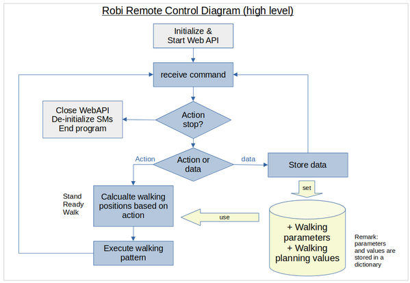
Please refer to attached picture “Robi Control Structure”. You can find the second page in the next step.
I opted for a modular approach so main functions are in separate modules. This reduces effort in testing and enables re-use. Although this Step is generic, I added function and module names of the implementation for Robi, for your convenience. References to functions and modules are in italics.
Initialization and start up:
Numbers in bullet points below are in the sequence of startup.
- Robot control is started by importing robi.py, the main program, which imports other modules as needed. Remark: two modules are provided: robi_web.py to start a small Web server to control Robi over WLan, this should be the default, and robi_test.py to control Robi using an USB cable instead. robi_test.py is used for initial test of the hardware.
- Initialization of the state machines for the servos by calling init_sm() in module cfg.py. PWM stays turned off at this time, to avoid accidental servo movement
- Connection to WLan by calling connect() in module wifiConnect.py.
- Remark: WLan credentials (SSID and passphrase) are set in module wifiConnect.py
- If connection cannot be established right away, 10 re-tries are made. If still no connection the program exits.
- Starting of the Web server in robi_comm.py to expose the API at port 8081 at the IP address obtained by connecting to the WLan. The Web server runs until a “stop” action is requested, which shuts down the robot. A reset or power off/on cycle is needed to restart the robot.
- in the main program robi_web.py (or robi_test.py) exceptions are managed
The Web server's API can be used to:
- set walking parameters (CoM, delay, micro step width, friction*)
- set values for walking planning (target distance, single step width, leading leg**)
- executing actions (stand upright, go to ready position, walk, stop)
- Receive status information
- Remarks:
- all parameters, planning data and status are stored in module cfg.py
- * friction is not yet implemented, depending on the surface Robi walks on target distance may not be reached. By using parameter friction this can be corrected)
- ** starting with the left leg is implemented, starting with the right leg will do nothing (to be implemented later)
Remarks:
- It is recommended to connect the USB interface of the RP2040 pico when you start the first time or need to debug. All modules print out status and debug information to the USB interface.
- I implemented three debug levels. The level is defined in module cfg.py by setting the value of variable debug to: 0=no info, 1=high level info, 2=detailed info.
- Additionally many modules have print statements commented out. Remove the comment “#” infront of the print statements to get more detailed information
Step 5: Basics: Walking Pattern Generation
The attached chart shows the modules and their functions for walking pattern generation and execution.
Definitions and constraints:
There are many degrees of freedom if we create a walking pattern, so we need to take some definitions to limit them. The robot hardware we built has some mechanical constraints and finally there is physics we cannot ignore, e.g. if we move the Center of Mass (CoM) outside the support area, which is basically our robots foot, the robot will tilt and fall.
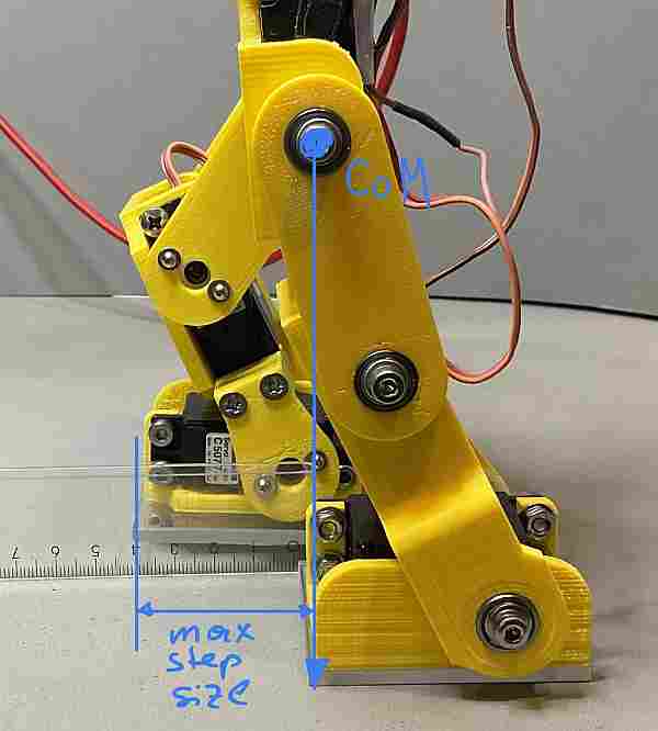
The Center of Mass (CoM):
- the maximum CoM off the ground is the length of the legs while Robi stands straight. For Robi this is 10.7cm.
- the minimum CoM is 9cm by experiment. If we move the CoM lower servos will start to block mechanically while walking. If servo calibration is done properly no damage will happen.
- the CoM moves together with the moving leg. This limits the step size, but is easier to calculate and control.
- the CoM needs to be inside the support area of at least one foot. From ankle to the tip of the foot we measure 4cm, thus the maximum step we can take is 4 cm. We could try to take larger steps, but Robi will start to fall forward if the CoM goes beyond the tip of the supporting foot. This can be controlled by fine tuning the walking parameters, but I opted for now to limit the step size. See picture to illustrate that constraint.
Walking pattern:
- the resting position is Robi standing straight, the CoM is at its maximum height.
- Walking starts with lowering the CoM to the ready position, still both legs on the ground. Typical values for Robi are between 9.5 and 10.5 cm.
- The CoM will always stay at the height of the ready position while walking (see Step 2 Inverse Kinematics)
- We start with a simple walking pattern, starting with the left leg:
- Left leg is lifted straight up to a safety height above the ground to avoid obstacles
- Left leg is moved forward a defined step width
- The CoM is moved the same distance forward as the left leg
- Left leg is moved straight down to the ground
- Right leg is lifted straight up to safety height
- Right leg is moved forward the defined step width
- Right leg moves straight down to the ground
- The walking pattern can be more complex, of course. It is a matter of implementing the algorithm and adjust the inverse kinematics, if required.
Optimization:
- Experiments show: if the walking pattern is executed at full servo speed, Robi will not walk nicely, because the servos are programmed in sequence. As a result the first servo will execute the full movement right away, the second servo will respond with a delay and the third servo will lag behind. At a smooth surface the standing foot may even slip backwards instead of the moving leg moving forward. To achieve a smoother walk:
- Lifting the leg can still be done in one move
- moving the leg and the CoM forward will be split into many smaller steps, let's call them micro steps. The servos will still be programmed in a sequence, but with many much smaller movements.
- Robi is walking with one speed only, which is pretty fast. To allow for speed adjustments and slower movement
- a delay is introduced. Once a micro step is executed the controller waits the delay value of time before the next micro step is executed. Be aware if the dealy is too large, Robi might tilt and fall
- the step size can be reduced, so many more steps are needed to make the target distance.
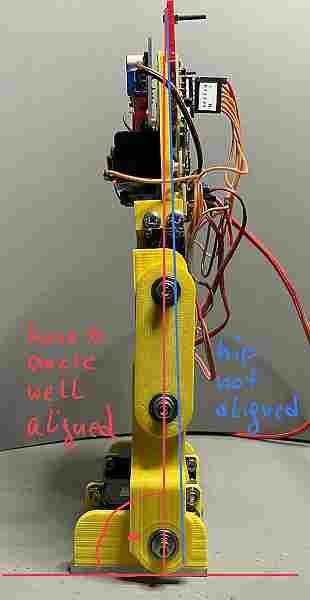
- You might see Robi walking in a circle instead of a straight line. One of the most probable causes is the servo neutral positions are not aligned properly. See Step 7 and (re-)do the servo alignment. Remark: I am using cheap servos with plastics gears. They are not totally accurate in reaching their position, so it could be that over time they go out of alignment. Then I re-do the calibration and update the values in the module robi_def.py.
Step 6: Development Environment

I am using Micropython version 1.19.1 as “operating system”.
This instructable assumes you have some basic knowledge on how to use a RP2040 PicoW board, load micro-python and python modules to the board. In case you need help, please find the step by step guide getting started with micropython on raspberry pi pico.
Load the software to the rp2040 PicoW:
To load Micropython version 1.19.1 or higher onto the RP2040 PicoW board, please follow the instructions on the Micropython download Website.
When you connect to the rp2040 picoW board after downloading and start micropython you get a message similar to below with the three chevrons >>> being the micropython REPL prompt:
MicroPython v1.19.1 on 2022-09-14; Raspberry Pi Pico W with RP2040
Type “help()” for more information.
A recommendation for a development environment:
You certainly can use your favorite IDE (Thonny, MU Editor, …) to edit and download micropython programs.
If you intend to further develop the modules with new functionality I'd like to recommend the tool “mpremote”. The documentation says: “The mpremote command line tool provides an integrated set of utilities to remotely interact with and automate a MicroPython device over a serial connection.”
In short: mpremote enables you to do all the editing work in a working directory on your PC with your favorite editor (e.g. I like to use sublime text 4).
When you are ready to test you open a terminal window, change the directory to your working directory and enter the command: mpremote mount . (do not forget the dot “.” , which indicates the current directory)
This mounts your working directory to micropython on the RP2040. You should get the REPL promt >>> of micropython. You can import and start your micropython programs from your working directory and get all the program output in your terminal window.
To test walk Robi you would enter >>> import roby_test.py
Should you need to correct an error, or like to continue programming, you can do that with your editor. To reload your program you do a soft reset of micropython (at the REPL >>> you hit CTRL-D) and import your program again.
This avoids that you have to download the program to the rp2040 flash memory all the time you do a change. When you are done with your development then you download the final program and you can run it independent of a PC.
Step 7: Initial Calibration of the Servos
If you have built Poor man's bi-pedRobot Hardware, you probably have your servos aligned and can skip to the next step. If you still need to do (or re-do) the alignment here is the procedure:
Copy pio_pwm.py from Step 1 to the RP2040 pico board.
Copy servo_alignment.py from this Step to the RP2040 pico board.
At the micropython >>> prompt type: import servo_alignment, which will start the program, and a welcome screen will be displayed (see picture).
Servo alignment:
The goal of the servo alignment procedure is twofold:
- to find the neutral position of the servo, which is the correct angle of each servo so that the robot stands straight with both feet aligned (see picture). This is also called the servo offset.
- to find the endpoints of servo movement, this is the maximum and minimum angle for each servo before it mechanically blocks. Not all servos can be moved to the full 0 to 90-degree range. E.g. the ankle servos can only move approx. between 10 and 75 degrees, otherwise, they mechanically block.
Write down the angle for the neutral position and the endpoints for each servo. This data is needed later for the Robot controller. E.g. when Robi has initialized all servos move to their neutral position and Robi stands straight.
Servo alignment procedure:
Connect and do the alignment procedure for one servo at a time, and keep the other servos disconnected
Preparation:
- at the first time mechanically disconnect the servo arm from the servo, as we do not know the servo's position at this time
- connect the servo power supply
- Hint: you can do the alignment for all servos with the same GPIO output e.g. Servo 0 @ GPIO0 at Pin1 of the pico board and connect the servos to their respective GPIOs when the alignment is completed.
Alignment Neutral position:
- Start the servo alignment program and enter the servo number e.g. Servo 0
- Enter the angle for the neutral position of the Servo:
- left ankle: 45 degrees
- left knee: 0 degree
- left hip: 45 degrees
- right hip: 45 degrees
- right knee: 0 degree
- right ankle: 45 degrees
- The servo should move to the neutral position. Then you can connect the servo arm so that:
- hip and knee – the legs- align in a straight line
- the ankles align 90 degrees with the legs
- Hint: depending on servo direction the neutral position for the knee servos could be 0 or 90 degrees
- Remark: with the given angles the alignment will likely not be perfect. If there is a small misalignment of a few degrees, it is ok at this time. The misalignment can be corrected with a fine adjustment later.
- Leave the servo connected and continue with the alignment of the endpoints.
The picture shows the final result after the neutral position alignment of all servos. It shows as well a small misalignment of the hip servo.
Alignment of endpoints:
- Start the servo alignment program (if not already running) and enter the angle for the neutral position.
- If the neutral position is 45 degrees:
- move the servo towards the zero-degree position in small steps, e.g. 45, 40, 35 …
- when the servo does not move anymore, this could be at 0 degrees or a larger number, you are at the minimum endpoint. If the servo starts humming loudly it blocks, then move back a bit by increasing the angle. Make note of the minimum angle.
- move the servo to the neutral position (45 degrees) and then move it towards the 90-degree position in small steps, e.g. 45, 50, 55…
- when the servo does not move anymore, this could be at 90 degrees or a smaller number you are at the maximum endpoint. If the servo starts humming loudly it blocks, then move back a bit by decreasing the angle. Make note of the maximum angle.
- Remark: the ankle servos will likely only move between 10 and 75 degrees.
- If the neutral position is 0 degrees:
- move the servo towards the 90-degree position in small steps, e.g. 0, 5, 10, 15…
- when the servo does not move anymore, this could be at 90 degrees or a smaller number you are at the maximum endpoint. If the servo starts humming loudly it blocks, then move back a bit by decreasing the angle. Make note of the maximum angle.
Neutral position fine adjustment procedure:
The initial alignment for the neutral position may not result in perfectly aligned legs and 90 degrees for the ankles. This can be achieved by tweaking the neutral positions of the servos.
- Start the servo alignment program and move the servo to the neutral position.
- Increase or decrease the angle by small steps, e.g. 1 degree, and watch the movement. You can do even smaller steps if needed. Increase/decrease the angle for each servo until the alignment is perfect: legs straight, left and right legs exactly parallel, and both ankles 90 degrees to the leg.
- Once done, create a little table containing the neutral angle and the endpoints for all servos. Safe it, these numbers will be needed by the robot controller. E.g. when the robot is initialized all servos are moved to their neutral position and Robi stands straight.
Remark: If you play with the servo alignment program, the pico state machines might not always properly de-initialize. If that happens they keep their memory allocated and you may run out of memory at a certain point. If you get an “OSError: [Errno 12] ENOMEM” do a soft reset (Ctrl-D). If a soft reset does not fix the problem, switch the power for the pico off and on for a clean micro python restart.
Read more: Poor Man's Bi-ped Robot Controller – Using RP2040 and Micropython