
Track the 230 VAC power line with your favorite HW using a small, efficient, and inexpensive circuit.
In my wireless doorbell tutorial I gave the advice about how to get a digital signal from a 12 Vac source so it could be read with any desired HW. That solution is not valid for high voltage, since the dissipated power is not acceptable. Hereby I describe another circuit that solves the issue.
If you want to track when a blackout occurs, there might be several solutions:
- Use a transformer to reduce the voltage, rectify it and adapt the signal to your system.
- Get whatever phone charger you have in your drawer, disassemble it, remove the output capacitor or change it for a lower value to get a quicker response, and there you have your 5 Vdc signal.
- Build the following explained circuit.
- P.S.: in the comments, there is JT proposing another very interesting solution with a 230 V neon tube and a LDR.
All these three solutions are perfectly valid, and it is easy to understand the pros and cons of each one. But in my opinion, the proposed solution is the cheapest, most efficient and smallest.
The circuit:
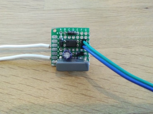
Explanation
For those not into electronics, here is the explanation of why does this work:
In the DC world, a capacitor is just a reservoir and ideally, in the stationary term, we can consider it as an open circuit (infinite impedance). But in the AC world, a capacitor represents an impedance, which is calculated as Z = 1/(2*pi*freq*C). In this case, with a 100 nF capacitor it would be equivalent to almost 32 kOhm. Applying the most popular formula in electronics (V = I*R), that gives around 7 mA current. But wait, I learned in the school that if the voltage is to much, I could reduce it with a voltage divider using just two resistors of the appropriate value; so, why not to do the same directly with a 32 kOhm resistor?? The answer is that the resistor would heat quite a lot (1.65 W), but the capacitor will not, because it doesn't consume real power, just reactive, that doesn't produce work (work = heat). That's quite a complex topic in electronics, that I'm not gonna explain here, but as a quick hint about how to think about it, imagine the capacitor as a flexible membrane; electrons do not pass through, as it would be the case with a resistor, but they push the membrane and their effect is transmitted to the electrons in the other side of the membrane. This way we take advantage of the costless high voltage drop in the capacitor and rectify the remaining low AC voltage as we would do with a regular transformer. To sum up, we did kind of the same as with a voluminous transformer (to reduce the voltage), but with just a simple inexpensive capacitor and consuming less power. Isn't it beautiful?
There is another difference in comparison with using a transformer: the current is limited. With a transformer, your low voltage capacitor (the 47 uF one) will absorb all necessary current until it reaches the rectified voltage, but that doesn't happen in the proposed solution, where the current is limited by the capacitor's impedance and the rectified voltage depends on the load. That makes the values of the capacitor and resistor in the low voltage side critical. Although slight different values could also work (electronics is rarely an accurate science in terms of component values), there is not much margin; but if using a transformer, one magnitude order variation in the resistor and capacitor wouldn't be a big deal.
Note for 110 Vac 60 Hz powernets
The represented circuit is meant for 230 Vac 50 Hz. To have the equivalent for 110 Vac 60Hz, just use a 150 nF or 220 nF capacitor instead of the 100 nF. In fact, a 150 nF capacitor suits even for both systems, but the proposed 100 nF has a quicker response.
Practical use
I use this circuit in my home automation system, attached directly to a Raspberry Pi, that is powered by a standard 5 V adaptor, but also in parallel with a power bank. Whenever a blackout occurs, the power bank keeps feeding the Raspberry, but the power outage is detected, sending me a notification thanks to Domoticz, my home automation system. Obviously, to send the notification, either you have your router with an UPS, as I do (15 € second hand), or you are connected to the mobile network. This way I can know exactly when and for how long the blackout happened and do some automatic tasks when the power returns, like switching off my Hue lights that inevitably turn on on power up.
Warning
I believe you are not dumb, but I shall warn anyway that you are dealing with high voltage that can cause you injuries and even death. Take care if you put this project in practice. I would recommend you, that once you have finished the circuit, you seal it somehow (hot glue perhaps? I love it), so you don't touch live parts accidentally when having your fingers around distracted with another thing that might be in the same box.
P.S.: Safety
I edit the article to add this section, in order to make more emphasis in the safety measures to be taken into account, as highlighted by some pals in the comments.
First, since we are dealing with high voltage (high voltage can be a relative concept, not only the definition of whatever technical field as noted in one comment below), I would recommend refraining of playing around with this if you are not familiar with electricity.
Second, as said originally, but it's good to repeat, you should seal the circuit, not only to avoid yourself to touch live parts, but also any other wire around, or whatever. By the way, I tried to burn hot glue and it seems to be safe enough.
Third, the above described circuit does not contain safety measures. A recommendation to protect the circuit against possible failures and surges would be as follows:
The MOV (V1) protects the circuit against surges, that could affect C1, and the fuse avoids the risk in case of a short in the circuit. Keep in mind the ratings are for 230 Vac, use appropriate values for other voltages.
Still I would like to note, that this circuit is not a bomb! If C1 is OK, it doesn't matter much whatever happens to the rest of the components, because the current would be limited to 7 mA. That's why I don't specify the ratings for BR1, C2 and R1. In the worst case, if the R1-U1 branch opens, the voltage at C2 will SLOWLY tend to increase until 325 V and eventually, if its rating is under that value, obviously it will fail in a no very espectacular way. In my opinion, it is better to use a low voltage rating capacitor to make it fail the soonest -> less energy (remember, current is limited, so a short circuit in C2 is OK). Using a 400 V electrolytic capacitor would be very voluminous and in the explained case, it would remain loaded with a dangerous voltage and energy. A zener in parallel to C2 would be even better, this way that capacitor will survive. The other important fact, is that the typical failure of film capacitors, as C1, is open circuit. In fact, against voltage spikes they react losing capacitance, but still working, due to its “self-healing” propriety.
Source: Power Outage Sensor