| Hardware components: | ||||||
 |
|
× | 1 | |||
 |
|
× | 1 | |||
 |
|
× | 1 | |||
|
× | 1 | ||||
|
× | 2 | ||||
|
× | 1 | ||||
|
× | 2 | ||||
 |
|
× | 1 | |||
 |
|
× | 1 | |||
|
× | 1 | ||||
| Software apps and online services: | ||||||
|
||||||
|
||||||
|
||||||
|
||||||
|
||||||
|
||||||
|
||||||
| Hand tools and fabrication machines: | ||||||
 |
|
|||||
STORY
Couple months back I bought a new 10th gen Honda Civic. The trim offered in my region lacked all ADAS features. Being an engineer with Embedded Systems background, I decided to build one myself.
Most ADAS combine camera with RADAR or LIDAR. I however only had camera to start with. It turned out I can do some basic tasks like Lane detection and departure warning but not much else, till the day Walabot arrived. Cameras are great of classification and texture interpretation but they struggle with 3D mapping and motion estimation. For automotive applications, Walabot can be used as a short range RADAR
Architecture
Generally we combine sensory data in a way that the resulting information has less uncertainty than would be possible when these sources were used individually.
Using different sensor types also offer redundancy in situations where one type of sensors would fail. That failure or malfunction can be caused by nature or it can be deliberate e.g jamming a RADAR.
A camera generally has trouble in fog, rain, sun glare and low- light. RADAR on the other hand, lacks the resolution of cameras. but it is great for measuring distances and looking through rain and fog. RADAR and camera can complement each other.
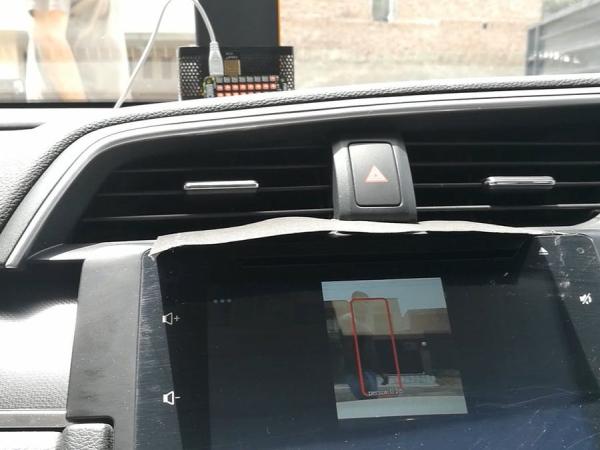
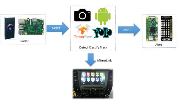
My algorithm raises an alert, if both Camera and Walabot has detected an object of interest in the same spatial coordinates
RADAR subsystem
Our RADAR is built using Walabot connected to a Raspberry PI v2 and communicating by MQTT over WiFi. I used WiFi hotspot built into the IVI unit. You can use a standalone hotspot but they tend to perform poor in automotive environment.
Background
Walabot gives you x-ray like vision but it does not use x-ray. Walabot has an array of linearly polarized broadband antennas that operate in frequency range: 3.3-10.3 GHz for the FCC model and 6.3-8.3 GHz in CE model.
If you are not familiar with Antenna Theory, the term polarization comes from the standing wave notation. In RF case, it means the orientation of Electric and Magnetic Field w.r.t direction of propagation. Linear polarized antennas typically have greater range due to the concentrated emission. I guess this makes sense for the Walabot case since we want to maximize the field of view.
At the heart of the Walabot there is a proprietary Vayyar VYYR2401 System-on-Chip for signal generation and reception. To connect via USB it uses Cypress FX3 controller.
Walabot can be configured in different modes for different use-case. They call it “scan profiles”.
- Short-range: penetrative scanning inside dielectric materials such as walls.
- Sensor: High-resolution images, but slower capture rate. Good for distance scanning:
- Sensor Narrow: Lower-resolution images for a fast capture rate. Useful for tracking quick movement.
I choose to use “Sensor” scan profile.
When Sensor profiles is used, Walabot processes and provides image data in a Spherical coordinates system. Ranges and resolution along radial distance and Theta and Phi angles.
SCHEMATICS
When Walabot is in its plastic case, USB connector side is the bottom.
You may ask the question why Raspberry PI v2? We are limited by Walabot SDK. The SDK is only available for x86 and Raspberry PI. I tried with Raspberry PI Zero first but the CPU was maxing out and I was loosing real-time detection capability. When I traded up to a Raspberry PI v2, things became smoother. I still think we loose samples but it seems to be workable for my use case.
Read more: Pre-Collision Assist with Pedestrian Detection – Honda Civic


