Introduction
You can use the Pi to drive a Liquid Crystal Display (LCD) to display all sorts of information: it could be date, time, system status, disk utilisation, MAC and IP address, etc.

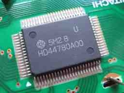
The HD44780 is the main driver chip but this is limited to two rows of eight characters each and so for larger LCD modules one or more slave Hitachi HD44100 chips are used. These convert the serial data from the HD44780 into parallel for passing to the display.

I started off with Matt's program but added a few enhancements so that it calls GPIO.cleanup() at the end to close ports so that you do not see warnings if you run the program subsequently. I also had to add a short delay between telling the device which row I was going to write and actually writing it. Without a delay, the first character was sometimes omitted.
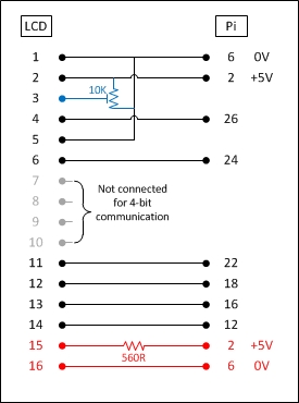
A further improvement is to connect a 10K variable potentiometer between the 0V and +5V lines and connect the output to the contrast pin (LCD pin 3). By varying the resistance between 0V and +5V you can find the optimum contrast for your LCD module. The connections in blue show the amendments to the original circuit.
Step 1
Connect up the components as shown in the diagram. The table of connections are shown below.
| LCD Pin | Function | Pi Function | Pi Pin | Slice of Pi Pin |
|---|---|---|---|---|
| 1 | GND | GND | P1-06 | GND |
| 2 | +5V | +5V | P1-02 | 5V0 |
| 3 | Contrast | GND | P1-06 | GND |
| 4 | RS | GPIO7 | P1-26 | SPI_1 |
| 5 | RW | GND | P1-06 | GND |
| 6 | E | GPIO8 | P1-24 | SPI_0 |
| 7 | Data 0 | |||
| 8 | Data 1 | |||
| 9 | Data 2 | |||
| 10 | Data 3 | |||
| 11 | Data 4 | GPIO25 | P1-22 | GP6 |
| 12 | Data 5 | GPIO24 | P1-18 | GP5 |
| 13 | Data 6 | GPIO23 | P1-16 | GP4 |
| 14 | Data 7 | GPIO18 | P1-12 | GP1 |
| 15 | +5V via 560R | P1-02 | 5V0 | |
| 16 | GND | P1-06 | GND |
If your display does not have pins 15 and 16 you can ignore the backlight connections.
Step 2
Download the program to your Pi. The easiest way to do this is to use wget from the Pi command line. This will copy the program to your current directory.
wget http://www.noveldevices.co.uk/rpdl/lcd.py
Step 3
Run the program as root. The program just displays some text on the LCD – it doesn't ask for any input and runs for about four seconds because of the delays programmed.
sudo python lcd.py
If you would like a program that lets you enter the text yourself, try this.
wget http://www.noveldevices.co.uk/rpdl/writelcd.py
sudo python writelcd.py

