
TESTS
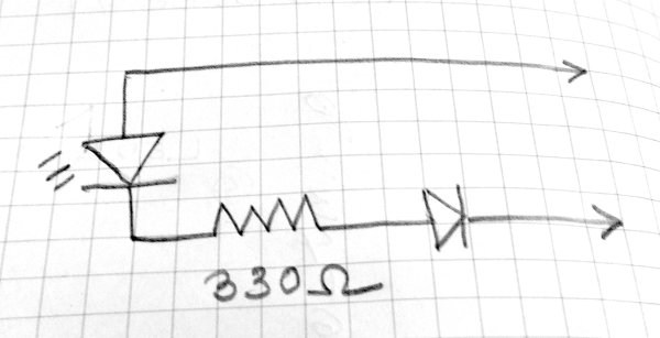
(1) On the Quick2Wire boards there is a 3-pin male header with pins for 5V, 3.3V, GND. I attached the test circuit to 5V and GND — it glowed as it should. Same for 3.3V and GND. So I decided that the board was probably working.
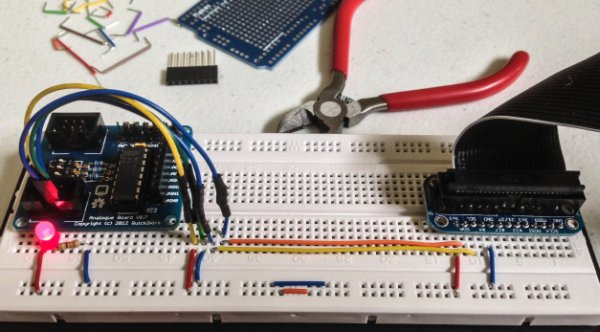
 (2) I left the black lead of the tester attached to GND, inserted a length of wire bared at each end into the other lead, and then into GPIO pin on the board labeled
 p0 on the board. This pin is one of a set of ten, labeled GND, p0, p1, …, p7, 3v3. Result with blink.py again: nada.
(3) I realized that I was confused about the various systems of pin numbering — GPIO, BOARD, Wiring Pi. So I modified blinktest.py to give the option of using any of the three systems:
   $ sudo python blinktest.py -g 18    # Blink LED on GPIO pin 18
   $ sudo python blinktest.py -w 1     # Blink LED on Wiring Pi pin 1
   $ sudo python blinktest.py -b 12    # Blink LED on RPi board pin 12
 The code for
 blinktest.py is at github.
With the blinktest.py and the test circuit in hand, I discovered that (a) the Quick2Wire board uses GPIO numbering on the Python side but Wiring Pi on the labels of the GPIO pins; (b) The jumper LED_ENABLE determines whether Wiring Pi pin 1 or LED is active. (c) I could not get Wiring Pi pin 2 to blink the test circuit. I’ll try swapping out the RPi later to see if it is at fault.
For more detail: Quick2Wire Interface Board – Assembly and Troubleshooting