
A Raspberry Pi 4 as NAS server with two WD red 4TB out of an old 19″ power amplifier case. (Hard- and software.)
Things used in this project
Hardware components |
||||||
 |
|
× | 1 | |||
Story
I had played around with the NAS feature of my router in the past, but quickly reached its limits. Since then, I was looking for a NAS solution for my whole family. Best to build it myself. I already had a few Raspberry Pis at home and when the PI 4B came out, this was the perfect moment to get this project started.
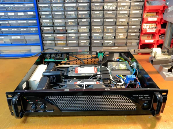
Around the same time, a power amp at my school broke. Since I am involved in sound engineering there, it was no problem to get hold of it. So, I had a case in which all components would fit.
This project is divided into two parts:
In part 1 we take care of the hardware, i.e., the cabling of the individual devices and especially also the installation in the power amp case.
In part 2 we will install the operating system and set up the NAS.
If you are only interested in the software part and setting up the NAS with Ubuntu Server, you can jump straight to the second part.
The complete project and associated code can be found on GitHub (https://github.com/JJandke/RaspberryPiNas).
Attention! Working on mains voltage is life threatening and should only be done by qualified personnel. Some steps shown here should only be done if you know exactly what you are doing. Furthermore, a multiple socket, as shown here, should never be used for permanent installations.
Specs:
- Raspberry Pi 4
- 8 GB DDR3 SDRAM
- Gigabit Ethernet
- 4 TB RAID 1 Storage
What you need:
Note: For a pure Raspberry Pi 4 NAS without amp case, we only need those articles in bold.
- Raspberry Pi 4B (I recommend the 8GB RAM version, as it is not much more expensive compared to other NAS solutions)
- Power supply (PSU) for the Pi (5V, 3A, 45W, UBS-C, surge- and overload protection)
- Micro SD card (32GB)
- Active cooling case for the Pi
- USB 3 Hub (This turned out later)
- Active USB-SATA adapter
- Hard drives (4TB WD red)
- 24V Power supply for the case fans (24V, 4.5A)
- 2 relay module (to switch the two case fans and the fan on the Raspberry Pi)
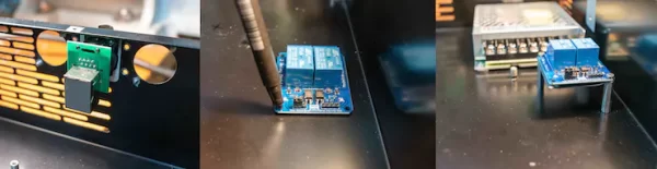
- Ethernet feedthrough (To connect an Ethernet cable to the case, as it would be with a real server)
- Ethernet patch cable (20cm)
- Switch (250V, 10A, for the Case)
- Fuse (4.5A)
- MC 7805 (Fixed voltage regulator)
- Capacitors (2200µF, 10 µF, 100nF – more details later)
- Diode (1N4001)
- Jumper cables

Part 1 – The enclosure (not important for the NAS itself)
Mounting the devices:
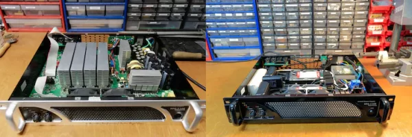
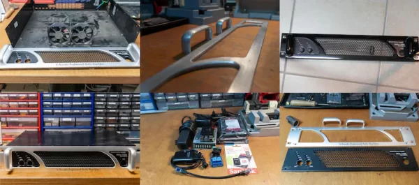
After opening the 19″ case, and removing the actual PCB, I was also able to unscrew the front panel and get access to the fans. Of course, these had to be cleaned first. I decided to further disassemble the front panel and spray paint it completely black. In order for the paint to hold better, I had to sand it down a bit.
Then I had to think about the actual allocation of the devices in the case. This was only possible to a limited extent before, because I didn’t have any specifications of the power supplies for the USB-SATA adapters. I had originally wanted to take a black multi-socket, but the plugs there were arranged at an 45° angle, so that the power supplies would then have been too high and would no longer have fit into the housing. Therefore, I had to search for a multi-socket with straight plugs.
Attaching The Parts
Now that I knew what should go where, I could start attaching the parts. The Ethernet feed through I could simply attach to the place of a previous speakOn port, for this I only had to drill two holes for the screws. For the relay, the 24 V power supply and the Raspberry Pi, I marked the holes and punched them so I could drill them with a 2.5 and 3mm drill bit. I was able to immediately screw the 24V power supply to the bottom of the case. But since the relay module was not insulated at the bottom side of the PCB, I had to mount it on spacers and attach a small plastic sheet.
I had long been wondering how I would mount the Raspberry Pi. In the end the best solution was to mark the four holes of the base plate with a scriber on the bottom of the amp and then screw the Raspberry Pi case to the power amp case with longer screws. Since the fans were clean again in the meantime, I could screw them into the case as well.
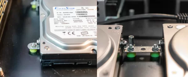
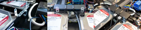
In order not to damage the hard drives during assembling the NAS, I took two old ones to mark the proportions. Then the hard drives were fixed with metal brackets. To allow air to get under the hard drives and reduce vibrations at the same time, I packed rubber spacers between both, the metal brackets and the case bottom.
AC wiring:
I decided to use the screw terminals on the 24V power supply to be able to connect the multisocket there. So, I had to remove the plug and strip the three stranded wires. I crimped ferrules onto the stripped ends and then screwed them (L2, N2, PE2) to the AC input side of the terminal block on the 24V power supply.
- From the incoming mains cable, I was able to connect the neutral conductor (N1) directly to the power supply, using a wire end ferrule.
- The phase (L1), I first connected to a 4.5A fuse. In my case, I was able to insulate the solder joints of the fuse holder well with heat shrink tubing and electrical tape.
- Then L1 was looped to the switch (250V, 10 A). There I used insulated cable lugs to be able to plug and unplug the switch easily. Next, the phase was pulled back to the power supply. Since I have an illuminated switch, I also had to connect the neutral (N3) to the switch.
- Because only two cable ends fit on the terminal strip of the 24V PSU, this neutral conductor (N3) had to be connected with a terminal plug.
- I also screwed the protective conductor (PE2) of the multiple sockets to the terminal strip of the power supply.
- In order to be able to connect the protective conductor of the mains cable and the power supply (PE3) and the incoming cable (PE1) with the housing, I have sanded down an unpainted area again and screwed both protective conductors using a toothed ring.
After an isolation test, I was able to plug it in for the first test. Fortunately, nothing blew up in my face, nothing exploded, and everything behaved as it should… except the switch… Wiring this power switch was a bit difficult, as it had an LED that was supposed to indicate if the switch was set to on or off… but it was not quite clear in which positions what happened. So, it took me a few tries before I knew the correct wiring, as the manufacturer did not include instructions.
Now that the AC part is done, I'll take care of the DC part.
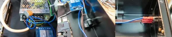
DC wiring:
This seems complicated because there are many cables, but it is relatively simple.
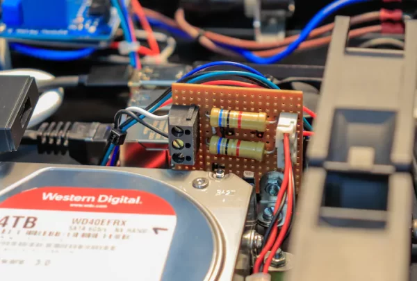
- To reduce a few cables and to be able to connect the fans well, I soldered a board to which I can plug both fans on one side and the 24V is connected on the other side. GND goes directly to the power supply and +24V are switched via relay 1. As it turned out later, the fans vibrated very strongly at 24V. At 20V, however, they ran quietly. Therefore I soldered a 85 Ohm power resistor in front of each fan. From the fan of the Raspberry Pi you can also plug GND directly to a GPIO. I connected the +5V with a jumper cable to relay 2 and led it back again, so I didn't have to cut and solder a cable. This would make the fan more replaceable.
- To switch the relay, we need to connect +5V (VCC) and GND (GND) from the Raspberry Pi as power supply to the relay module. We also need GPIO 04 (IN1) and GPIO 17 (IN2) to switch the relays. The jumper has to be set between VCC and RVCC. Now the relay would theoretically already work, but the Raspi would not be galvanically separated from the relay module.
- To achieve this by using the optocouplers on the PCB, the jumper must be removed and a voltage of +5V must be connected to RVCC and GND.
- Since I don't have a 5V voltage source in the case, I built myself a voltage converter with a fixed voltage regulator with the following schematic:
- On the in pin of the MC7805 +24V are applied. Also an electrolytic capacitor is connected between +24V and GND. The middle pin (GND) is also connected to GND and the Out pin is connected to RVCC on the relay board. Between the out pin and GND an electrolytic capacitor with 10µF and a ceramic capacitor with 100nF are connected. To protect the MC7805 from a too high voltage at the out pin, a 1N4001 diode is connected between In and Out. The capacitors smooth the voltage. The GND of the circuit is connected to GND on the relay board.
- Because 19V drops at the fixed voltage regulator, it can get very hot. Therefore I took an old heat sink, which was previously installed in the power amp, and attached the MC7805 to it. I used a fixed voltage regulator instead of a DC/DC converter, because I had one at home. In addition, the 5V are only needed for the switching operations of the relay. Therefore the heat sink is theoretically not necessary. But since I might need the 5V output for other stuff and it does look good, I decided to use it.
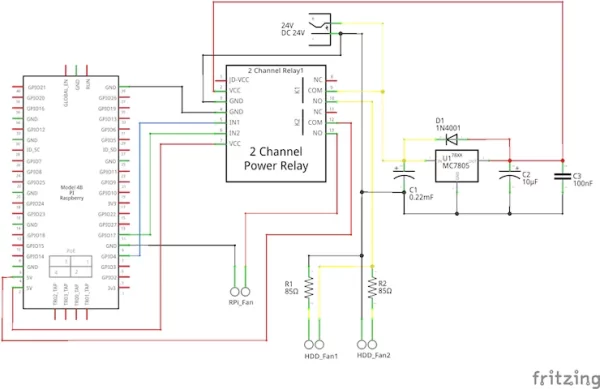
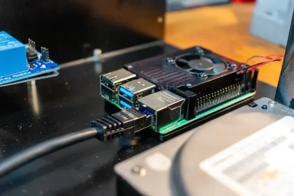
- Now all that's left to do is plug in the power supplies, connect the hard drives to the Pi, and create a connection with the 20cm patch cable between the Pi and the Ethernet feedthrough.
At this point it is important to add that it turned out later that you need an additional active USB hub between the Raspberry Pi and the active SATA USB adapters. When setting up the NAS, I struggled almost continuously with one of the disks being kicked out. sudo dmesg always returned errors that looked like this: over current change #54. There were other errors, but they were software related. After weeks of trying and researching I found someone with the same problem. His hard drives were also thrown out, although he also used active SATA USB adapters. Indeed. With an active USB hub I didn't get these error messages anymore. Interesting to know is that the active USB hub drew only 0.2A(DC) in IDLE and almost 1A(DC) in use. From this I conclude that the active adapters could not supply enough current. Now that the Raspberry Pi has been expanded with more USB3 ports, I'm also thinking of moving the operating system to an SSD, as these are more durable than SD cards.
Of course, good cable management is important, so that cables do not unplug themselves and that it is easier to upgrade later.
To stop dust that would be sucked in by the fans, I sandwiched a strip of filter floss for servers between the chassis and the fans.
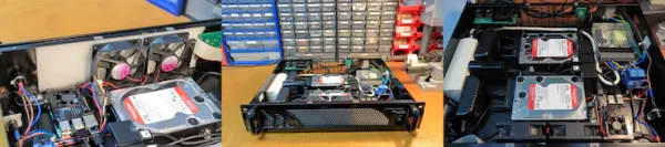
After flashing the Micro SD card (See Part 2) I was able to insert it into the Raspberry Pi and then attach the black painted front panel as well as the lid.
About switching the fans: Since the fans do not support PWM out of the box, it would be an idea to control the fans with MosFets instead of just a relay, to control their speed proportional to the temperature.
Now we continue in part 2, since we have already done everything that has to do with hardware.
Part 2 – Software
Install operating system
- To get the operating system onto the SD card, we use the Pi imager.
- There we select Choose OS -> Other general purpose OS -> Ubuntu -> Ubuntu Server 20.XX.x LTS (RPi 3/4/400).
- And then choose your SD card.
- Then press “Write” The process took me about 6 minutes.
Get the IP of the Raspberry
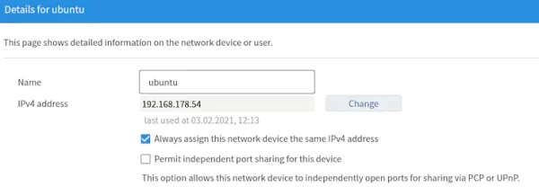
- After the SD card is in the Pi and it is turned on, it should appear on your router's user interface after a few seconds.
- At my Fritz!Box you can find the IP under Home Tetworks -> Mesh -> Other connected or registered home network devices.
- There you should give the device a static IP, so that you don't have any problems later when mounting e.g. in fstab.
Access the Pi via SSH
- To get access to the Raspberry Pi via SSH, we open a terminal on the PC and type:
ssh ubuntu@ubuntuorssh ubuntu@"IP_of_your_pi". - the default password is
ubuntubut the password should be urgently replaced with a strong password, otherwise an attacker will have access to all data stored on the NAS. - After that you will be logged out and have to log in again with your new password.
First steps on a new OS
Hints and tips
- Use
tabin terminal for auto-complete. - Exit nano with
Ctrl+xand confirm changes withy. - Select a text section in nano:
Alt+A+Mand then move with thearrowkeys.Ctrl+arrowkey then selects the whole paragraph at once. - Cut selected text in nano:
Ctrl+K
Update the Raspberry Pi
sudo apt-get update
sudo at-get full-upgrade
If errors occur here, just rebooting will help.
Make SSH more secure
Note: Since the NAS will only be accessible from the home network anyway, this is not absolutely necessary. This measure helps to make attacks on port 22 useless, but with a portscan you can also find out the actually used port. Therefore, a strong password is more important for every user. More help would be provided by fail2ban and access via certificate.
- For this we need to change the default SSH port and disable root login. This is done in the SSH configuration file under /etc/ssh/sshd_config:
sudo nano /etc/ssh/sshd_config- Here we have to remove the “#” in line
#Port 22and change “22” to any other port (e.g. 2846). - Also, in the line
#PermitRootLogin prohibit-password,the “#” should be removed and “prohibit-password” should be replaced by ” no”. - This should look like this:
Port 2846
#AddressFamily any
#ListenAddress 0.0.0.0
#ListenAddress ::
#HostKey /etc/ssh/ssh_host_rsa_key
[...]
# Authentication:
#LoginGraceTime 2m
PermitRootLogin no
- To make the changes take effect immediately, we restart ssh:
sudo /etc/init.d/ssh restart
Allow selected port in the firewall
Since we changed the default port of SSH, sudo ufw allow OpenSSH won't work anymore. Therefore, we need to use the following command to allow the newly selected port:
sudo ufw allow 1636- Now the port must be specified when logging in via SSH:
ssh ubuntu@ubuntu -p 2846
Change hostname
Since I have installed several Ubuntu servers and want to recognize my NAS better in the home network afterwards, the hostname will be changed. Note: After that the RPi is no longer reachable via ssh under ssh ubuntu@ubuntu -p 2846 but under ssh ubuntu@rpi-nas -p 2846.
- With
hostnamectlwe can display the current hostname:
$ hostnamectl
    Static hostname: ubuntu
          Icon name: computer
         Machine ID: e5e5d4e8666c456488d91bc2735712d0
            Boot ID: 1fdeecd84e8f48c499c520978bc60358
   Operating System: Ubuntu 20.04.2 LTS
             Kernel: Linux 5.4.0-1029-raspi
Architecture: arm64- With the
set-hostnameoption we can set a new hostname:
sudo hostnamectl set-hostname rpi-nas- Then we have to add the line
127.0.0.1 rpi-nasto the/etc/hostsfile:
sudo nano /etc/hostsIt should then look something like this:
127.0.0.1 rpi-nas

# The following lines are desirable for IPv6 capable hosts
::1 ip6-localhost ip6-loopback
fe00::0 ip6-localnet- The last thing to do is to change a value in the cloud.cfg file:
sudo nano /etc/cloud/cloud.cfg- Search here for
preserve_hostname:and change the value totrue - To make sure everything worked, we run
hostnamectlagain.
$ hostnamectl
    Static hostname: rpi-nas
          Icon name: computer
         Machine ID: e5e5d4e8666c456488d91bc2735712d0
            Boot ID: 1fdeecd84e8f48c499c520978bc60358
   Operating System: Ubuntu 20.04.2 LTS
             Kernel: Linux 5.4.0-1029-raspi
       Architecture: arm64
Add non-root user
The last thing we do is to add a default, non-root user, which we will work with from now on.
- To do this:
sudo adduser config- Add the user to the sudo group:
sudo usermod -a -G sudo config- Now we switch to the new user and run a command that requires root right to make sure everything worked:
sudo su - config
 sudo apt-get update
Python scripts to cool the NAS
Cooling the Raspberry Pi
- First, you need to install some packages:
sudo apt-get install python3-pip
sudo pip3 install Rpi.GPIO
pip3 install gpiozero
pip3 install pigpio
sudo apt-get install rpi.gpio-common
sudo apt-get install python3-rpi.gpio- Then the group
gpiomust be created, the current user (config) must be added and the group must get rights for the GPIOs:
sudo groupadd gpio                  # Add the group
sudo usermod -a -G gpio $USER       # Add the current user to the new group
sudo grep gpio /etc/group           # Assure that everything is working
sudo chown root:gpio /dev/gpiomem   # Change the gpio owner to root
sudo chmod g+rw /dev/gpiomem # Add read and write permissions- Alternatively, the current user may also own
gpiomem:
sudo chown root:$USER /dev/gpiomem- Now we create another folder where the python scripts will be placed, and also the python script itself. The code that needs to be inserted is found on GitHub:
mkdir code
cd code
mkdir python
cd python
nano cooling_pi.py  # now paste the code from GitHub
sudo chmod u+x cooling_pi.py # Make the script executable- To ensure that the Pi is reliably cooled after each reboot, we add the following line to the crontab. To log any errors that occur, we also create a log file:
cd log/
touch cron_user.log
crontab -e
     @reboot python3 /home/config/code/python/cooling_pi.py > /home/config/log/cron_user.log 2>&1    # Insert this line.
Cooling the HDDs
- To be able to read out the temperatures of the hard disks, hddtemp must be installed:
sudo apt-get install hddtemp- The following line can be used to read out the temperature for a hard disk:
for i in /dev/sdX ; do sudo hddtemp sata:$i; done- For the script we create a new folder for shell scripts in the directory./code. There we will create a script for each disk (code on GitHub) Since the readout requires root rights, but the python script is executed by a non-root user, the owner of the shell scripts must be changed to root, as well as the file rights must be adjusted.
cd code/
mkdir shell
cd shell/
nano sda_temp.sh        # For HDD1
nano sdb_temp.sh        # For HDD2
sudo chown root:root sda_temp.sh sdb_temp.sh        # Change the owner
sudo chmod 755 sda_temp.sh sdb_temp.sh      # Assign the relevant file permissions
sudo visudo    # To avoid the need to enter a password, insert those two lines
     config ALL=(ALL) NOPASSWD: /home/config/code/shell/sda_temp.sh
config ALL=(ALL) NOPASSWD: /home/config/code/shell/sdb_temp.sh- Now we create the python script and add it to the crontab.
cd code/python/
 nano cooling_hdd.py     # now paste the code from GitHub
 sudo chmod u+x cooling_hdd.py       #  Make the script executable
 crontab -e
     @reboot python3 /home/config/code/python/cooling_hdd.py > /home/config/log/cron_user.log 2>&1       # Insert this line.