
Not only is the Raspberry Pi 4 bursting with new hardware features but under the hood there are some extra GPIO functions to make life a bit easier, allowing users to expand their peripherals to their projects without requiring additional hardware In particular there are a bunch of extra I2C, UART and SPI interfaces that can be used on the Raspberry Pi 4.
GPIO pinouts
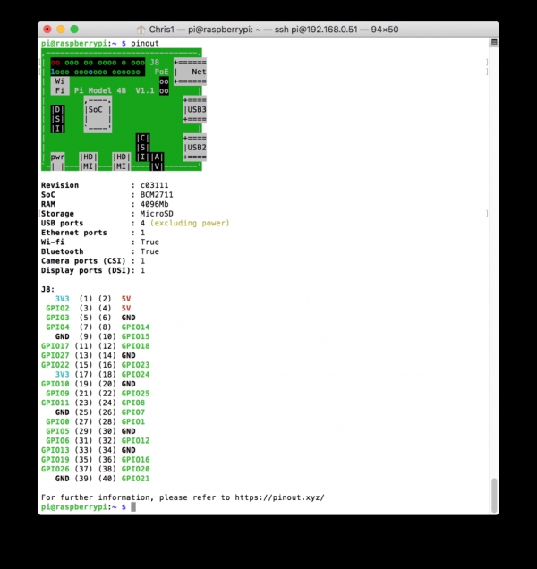
You can find a full list of GPIO pinouts on the Raspberry PI 4 itself, simply go to the command line and type in pinout.
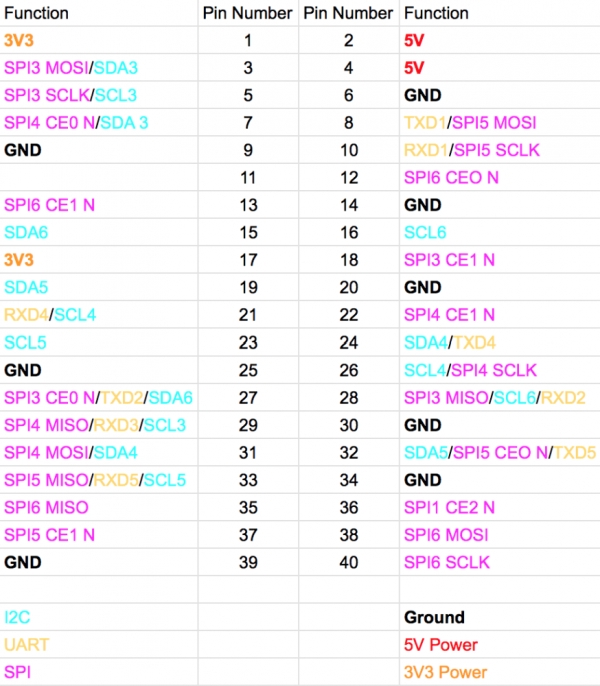
Below is a list of all the new Raspberry Pi 4 extra pinout features:
GPIO – General Purpose Input Output Pins
These digital pins can be programmed to receive digital inputs or output a digital signal. The Raspberry Pi uses a 3V3 logic on each GPIO pin, which means that 3V3 is a digital 1 (ON) and 0V is digital 0 (OFF). Therefore you can connect and digital component to the Raspberry Pi and either provide a 3V3 (ON) signal to it or receive a 3V3 digital signal providing the current is no more than 16mA.
I2C – Inter-Integrated Circuit
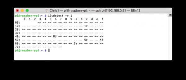
This is a fairly common type of communication between devices, it works by having a master and a slave. The master in this case is the Raspberry Pi itself and the slave devices are hardware peripherals that would normally extend the functionality of your projects. Whats great about I2C is that you can connect hundreds of devices up to the same master using the same two-wire interface, providing that each device has a different I2C address. You can access the interface and see which devices are conencted by using the following linux command:
sudo i2cdetect -y 1
Where “1” is the master interface. The Raspberry Pi 4 has 6 in total.
SPI – Serial Peripheral Interface
SPI is another type of communication protocol for communicating between devices. It also uses a master/slave setup but is primarily used in short distances between a main (master) controller and peripheral devices (slaves) such as sensors. SPI typically uses 3-wires to communicate with the Raspberry Pi; SCLK, MOSI and MISO. Before using SPI you need to enable it within the Raspberry Pi configuration menu:
UART – Universal Asynchronous Receiver/Transmitter
Unlike I2c and SPI, UART is not a protocol. UART (Serial) is a physical circuit designed to transmit and receive serial data. UART does not require a clock signal, hence why it is asynchronous. This minimises the required wires need to to send and receive data but it also requires some extra data to be sent with the packets for error checking such as a start bit and a stop bit. Typically with regards to the Raspberry Pi UART is used in a headless setup, which means no GUI or other interface. Instead you can connect the Raspberry Pi to your Desktop/Laptop or other device and communicate with it over UART using the command line interface. This method is for the more advanced users since it requires a bit more know how in setting it up.
Another application, which is typical amongst Raspberry Pi users is to connect a Arduino UNO board to the Raspberry Pi, since the Pi has limited analog functionality.
Source: Raspberry Pi 4 Pinout