
The Raspberry Pi is a great little educational computer, but all models of the Raspberry Pi miss a critical ingredient for electronics experiments – an Analog to Digital converter.
I am constantly working on upgrading my lab, and one of my needs is to measure many channels of analog signals, with reasonably high precision.
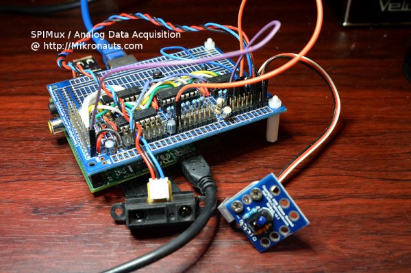
I decided to take the time to document a custom Raspberry Pi based data acquisition system that I built to monitor up to 64 analog inputs (currently 24 are available) at two different voltage ranges.
As the project needs at least three (and up to eight) SPI devices, it incorporates an SPI demultiplexer circuit to generate eight chip selects from /CE1.
Problems
There are three issues that affect the precision, and number of channels, for this project:
1) Conversion Error
In the past, I just used Microchip’s excellent MCP3008 (eight channel, 10 bit ADC) and MCP3208 (eight channel, 12 bit ADC) which needs an analog voltage reference.
Using the 5V power supply as the analog voltage reference is the simplest choice, but the analog to digital conversion results will be relative to the fluctuating 5V power supply – which is effected by everything happening with the Pi, with 5% error being commonplace.
The simplest way to get more accurate results is NOT to use the systems 5V supply as Aref, but instead use an voltage reference such as a 2.5V Vref will allow measuring 0-2.5V analog inputs much more precisely.
Unfortunately, the most common range I need to measure is approximately 0-5V and often it would be nice to be able to measure more than 5V at times.
The simplest solution is to add a voltage divider on every analog input – for example, using two 10k precision resistors would allow accurately measuring 0-5V using a 2.5V voltage reference.
2) Number of Channels
As I mentioned earlier, I want to be able to measure many channels of analog data, so the eight channels present on an MCP3208 are not sufficient for my purposes.
Using both chip selects available from the GPIO header would allow for 16 analog inputs – but I need more than that!
There are two simple ways of solving this issue:
2.1) Add Analog Multiplexers
It is fairly easy to expand the number of channels using inexpensive analog multiplexers such as the 74HC4051 – just add an analog multiplexer in front of each ADC channel, and feed the output of the analog multiplexer to the divider.
Unfortunately, this increases the amount of wiring, and the multiplexer will add its own minute (but very real) error to the analog signal being measured.
The advantage of this approach is that these multiplexers are a lot less expensive than the analog to digital converters, you will need fewer voltage dividers, and by using three I/O’s as the multiplexer address, eight multiplexers and a single MCP3208 can support 64 channels of input.
The disadvantage for this approach is the internal resistance of the analog multiplexer needs to be taken into account with non-1:2 voltage dividers.
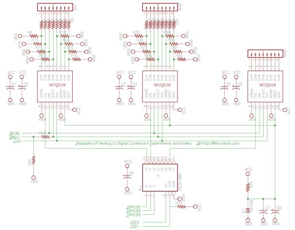
2.2) Create more chip selects and use more MCP3208′s
This is the more expensive, and slightly more accurate approach – but wait, the Raspberry Pi only has one SPI port, with only two chip select!
Fortunately it is very easy to generate additional chip selects using a 74HC138N 1:8 decoder, three I/O bits, and one of the existing chip selects.
I chose this approach in the past – and will do so again – due to the greater flexibility, as there is nothing that says that the eight devices have to be identical!
3) Input Voltage Range
The most common voltage ranges I need to accurately monitor these days is 0-3.3V and 0-5V however it would be nice to be able to monitor at least 0-6V in order to measure 5V power supplies and signals when they exceed 5V.
Instead of using a common 2.5V voltage reference, I decided to use a readily available 4.096V voltage reference.
A 4.096Vref means that the 12 bit conversion result from an MCP3208 is in mV so to get the voltage just divide by 1000. Makes the math easy
It also allows measuring up to 8.192V (in 2mV steps) by using a simple 1:2 voltage divider, and 16.384V (in 4mV steps) with a 1:4 divider.
For more detail: Raspberry Pi Analog to Digital Conversion Experiments and Howto