
In this article by Jack Creasey, author of Raspberry Pi Essentials, we will learn about the remote input/output technology and devices that can be used with the Raspberry Pi. We will also specifically learn about 1-wire, and how it can be interfaced with the Raspberry Pi.
The concept of remote I/O has its limitations, for example, it requires locating the Pi where the interface work needs to be done—it can work well for many projects. However, it can be a pain to power the Pi in remote locations where you need the I/O to occur. The most obvious power solutions are:
- Battery-powered systems and, perhaps, solar cells to keep the unit functional over longer periods of time
- Power over Ethernet (POE), which provides data connection and power over the same Ethernet cable which achieved up to 100 meters, without the use of a repeater.
- AC/DC power supply where a local supply is available
Connecting to Wi-Fi could also be a potential but problematic solution because attenuation through walls impacts reception and distance.

Many projects run a headless and remote Pi to allow locating it closer to the data acquisition point. This strategy may require yet another computer system to provide the Human Machine Interface (HMI) to control a remote Raspberry Pi.
(For more resources related to this topic, see here.)
Remote I/O
I’d like to introduce you to a very mature I/O bus as a possibility for some of your Raspberry Pi projects; it’s not fast, but it’s simple to use and can be exceptionally flexible. It is called 1-Wire, and it uses endpoint interface chips that require only two wires (a data/clock line and ground), and they are line powered apart from possessing a few advanced functionality devices. The data rate is usually 16 kbps and the 1-Wire single master driver will handle distances up to approximately 200 meters on simple telephone wire. The system was developed by Dallas Semiconductor back in 1990, and the technology is now owned by Maxim. I have a few 1-wire iButton memory chips from 1994 that still work just fine.
While you can get 1-Wire products today that are supplied as surface mount chips, 1-Wire products really started with the practically indestructible iButtons. These consist of a stainless steel coin very similar to the small CR2032 coin batteries in common use today. They come in 3 mm and 6 mm thicknesses and can be attached to a key ring carrier. I’ll cover a Raspberry Pi installation to read these iButtons in this article.
The following image shows the dimensions for the iButton, the key ring carriers, and some available reader contacts:
The 1-Wire protocol
The master provides all the timing and power when addressing and transferring data to and from 1-Wire devices. A 1-Wire bus looks like this:
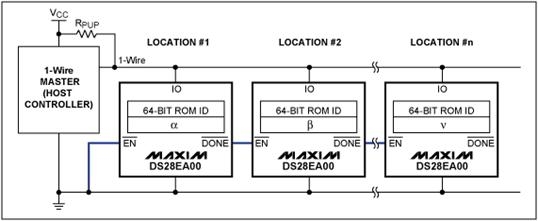
When the master is not driving the bus, it’s pulled high by a resistor, and all the connected devices have an internal capacitor, which allows them to store energy. When the master pulls the bus low to send data bits, the bus devices use their internal energy store just like a battery, which allows them to sense inbound data, and to drive the bus low when they need to return data. The following typical block diagram shows the internal structure of a 1-Wire device and the range of functions it could provide:
There are lots of data sheets on the 1-Wire devices produced by Maxim, Microchip, and other processor manufacturers. It’s fun to go back to the 1989 patent (now expired) by Dallas and see how it was originally conceived (http://www.google.com/patents/US5210846). Another great resource to learn the protocol details is at http://pdfserv.maximintegrated.com/en/an/AN937.pdf.
To look at a range of devices, go to http://www.maximintegrated.com/en/products/comms/one-wire.html.
For now, all you need to know is that all the 1-Wire devices have a basic serial number capability that is used to identify and talk to a given device. This silicon serial number is globally unique. The initial transactions with a device involve reading a 64-bit data structure that contains a 1-byte family code (device type identifier), a 6-byte globally unique device serial number, and a 1-byte CRC field, as shown in the following diagram:
The bus master reads the family code and serial number of each device on the bus and uses it to talk to individual devices when required.
Raspberry Pi interface to 1-Wire
There are three primary ways to interface to the 1-Wire protocol devices on the Raspberry Pi:
- W1-gpio kernel: This module provides bit bashing of a GPIO port to support the 1-Wire protocol. Because this module is not recommended for multidrop 1-Wire Microlans, we will not consider it further.
- DS9490R USB Busmaster interface: This is used in a commercial 1-Wire reader supplied by Maxim (there are third-party copies too) and will function on most desktop and laptop systems as well as the Raspberry Pi. For further information on this device, go to http://datasheets.maximintegrated.com/en/ds/DS9490-DS9490R.pdf.
- DS2482 I2C Busmaster interface: This is used in many commercial solutions for 1-Wire. Typically, the boards are somewhat unique since they are built for particular microcomputer versions. For example, there are variants produced for the Raspberry Pi and for Arduino. For further reading on these devices, go to http://www.maximintegrated.com/en/app-notes/index.mvp/id/3684.
I chose a unique Raspberry Pi solution from AB Electronics based on the I2C 1-Wire DS2482-100 bridge.
The following image shows the 1-Wire board with an RJ11 connector for the 1-Wire bus and the buffered 5V I2C connector pins shown next to it:
For more detail: Raspberry Pi and 1-Wire