Hi there. This post is not going to be on JavaScript but it will be a bit more centered on the Raspberry Pi and what I did today. As pointed out in an old blog post, I'm working on a software that creates streams of data and pass them through a topology. As data sink, I though it would be very nice to have a Raspberry Pi which gathers data from the environment, for example.
Today I started to implement something on the RPi. Nothing serious, but I wanted to test the GPIO. First of all I had to install some Python dependencies to read data from it
 $sudo apt-get update $sudo apt-get install python-dev $sudo apt-get install python-rpi.gpio
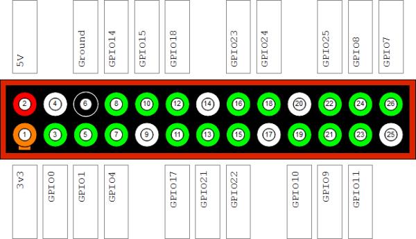
After this, I had to learn a little bit about the GPIO. The General Purpose Input/Output is an interface available on some devices capable of getting inputs and sending outputs. In the RPi, this is the male pins situated on top of the RPi logo in the latest devices.
The following schematics shows which pin corresponds to which usag
Today what I will do is connect a simple button and trigger some event on the RPi. The event will only be a print line saying something. The purpose of this test project was to get my hands dirty a little bit with the RPi by starting with something extremely simple.
 Components
– 1 Raspberry Pi
– 1 Ribbon
– 1 Breadboard
– Some wires
– 1 10k Ohm resistor
– 1 Button sensor
How to build
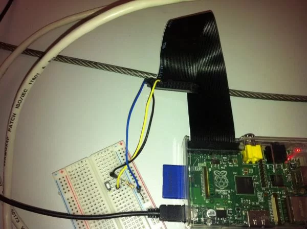
Place the button on the breadboard. On the row of one pin of the button, I had to connect one head of the resistor. The other head had to be connected on another row. On the same row of this head, then, I had to connect the 3v3 pin (pin 1) of the RPi. To do that I had to use the ribbon and then use a wire from the other end of the ribbon.
I have chosen to use the pin called GPIO17 on the image shown. From that pin I connected a wire which was placed on the same row in which one head of the button and one of the resistor were placed. Finally, the ground pin was connected to the other end of the button.
Code
The code was a simple piece of Python that gathered the input from the pin number 17. Here is it:
import RPi.GPIO as gpio
gpio.setmode(gpio.BCM)
pin = 17;
gpio.setup(pin, gpio.IN)

while True:
    input = gpio.input(pin)
    if input == False:
        print('button press');
        while input == False:
            input = gpio.input(pin);
Be careful and respect indentation as Python will complain otherwise. I have chosen pin 17 but any GPIO pin will work as long as you change it in your code. The code is extremely simple: with a while True it checks if the button has been pressed. If that is the case, then, it will print the message. While the button is pressed it will just fall into the second while statement.
To run the code, just do this
sudo python filename.py
And that's it. Here is a picture of what I built.