
After my recent posts on using the MCP23017 I/O expander with the Raspberry Pi several people have queried the connection of an I2C device running at 5v to the Raspberry Pi’s 3v3 I/O. The reason why this is safe in this case is that on an I2C bus the clock and data lines are open-drain lines that are pulled high and devices on the I2C bus pull them low to communicate, in this case the Pi is pulling the lines to 3v3 and it and the MCP23017 pull them low, this means the Pi is never exposed to the 5v supplying the MCP23017. As long as the slave device is happy to register the 3v3 as a high then everything will work fine.
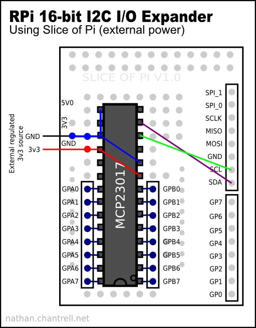
In my testing the Pi has worked flawlessly with the MCP23017 like this although as Selsinork pointed out in the comments on this post it is strictly speaking out of spec, a high shouldn’t really be any lower than 4v for the MCP23017 so in theory using 3v3 could cause reliability problems, it’s perfectly safe as far as the possibility of causing damage to the Pi is concerned though. That said, it does work in practice although YMMV and I suspect if you tried adding more MCP23017s or distanced it from the Pi that reliability would drop off rapidly.
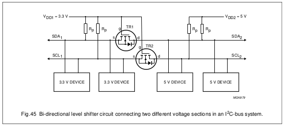 One way I had thought of to fix this had it been a problem was to use a bi-directional buffer IC such as the P82B96 at a cost of a few pounds but Selsinork tipped me off to a very cheap way to do this with just a couple of n-channel FETs,
For more detail: Raspberry Pi and I2C devices of different voltage