This project is the summation of various similar tasks to use a Raspberry Pi as a portable games emulator. It's heavily indebted to the excellent and funAdafruit PiGrrl project and DDG's great work to add sound to that project here.
Whilst I was happy with the results of the PiGrrl project, the fact that it used the Framebuffer to output to the TFT screen limited what emulators could run on it. So I decided to try something similar but using a more normal display method of the composite out port and a TFT screen which would allow me to run MAME4ALL, PCSX and various other emulators for things like the SEGA Genesis, Nintendo SNES, MS-DOS and of course the Atari Lynx.
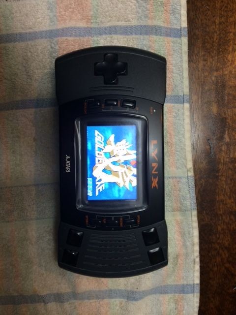
I always liked the Atari Lynx as a device (although I never had the pleasure of owning one as a kid). It's chunky, well-designed and the Atari Lynx 2 is wide enough that it should fit everything in relatively easily. So I thought I'd put it all in one of those.
Three introductory videos showing it in action and giving an overview of the project are above.
Apologies in advance for the lack of decent work-in-progress pictures as I'm writing this instructable retrospectively. However as most of the components are from Adafruit and the whole thing is heavily based on the PiGrrl project, those pages make useful guides as well.
Step 1: Hardware Components
1.) Atari Lynx (not working). I got mine from eBay available here. It's useful if the speaker still works as it can be re-used, but not essential. If it's not working when it arrives, you can always just buy another one for a couple of bucks. The rest of the old Lynx internals won't be used so if the screen's busted for example, it doesn't matter for this project.
2.) Raspberry Pi B+ available here. I used the B+ as the power consumption is supposed to be better and I obviously had more pins to play with.
3.) Adafruit Powerboost and Recharger available here. This allows the 3.7V battery to power the entire thing at 5V and also supports the recharging interface to a micro-USB cable. It's a nice bit of kit.
4.) Adafruit Lipoly battery, 3.7V and 2500mAh available here. I picked this as it's nice and flat so fits in the case nicely and offers a nice amount of power for the size and price.
5.) Adafruit breadboad friendly SPDT switch available here. As we won't be using any of the existing Lynx board we're going to need a new power button. This works nicely with the Powerboost/Recharging board above.
6.) Adafruit Stereo 2.8W Class D Audio Amplifier TPA2016 available here. We'll need to amplify the sound output from the Pi's composite audio/video out port and route it to the speaker. This is a nice board for this I think.
7.) **Optional if the on-board speaker doesn't work on the Lynx**. A Mini Metal Speaker w/Wires – 8 ohm 0.5W available here. The Atari Lynx speaker is preferable as it's quite good and fits nicely in the case already. If it doesn't play ball then you might want to get a couple of these or an equivalent to take its place.
8.) Raspberry PI B+ GPIO 40 pin ribbon cable available here. We'll plug one end (make sure it's the right end) into the GPIO ports of the Pi, and cut the connector off the other end. We'll split the wires out on that end and solder them to the Lynx FPC connector (for the buttons) and the Powerboost (for the power).
9.) **Optional and only required if you can't use the one that came with the Lynx** 14 pin 1.25mm pitch FPC connector available here. When I removed the FPC connector on the Lynx's original board, I bungled it completely and ruined the connector. So I had to buy another one which took some guessing as I wasn't sure of the pitch of the Lynx's FPC. After some trial and error this connector worked fine.
10.) 5V 3.5” TFT LCD screen available on eBay and Amazon etc.. I got minehere. Important note: I was lucky in that this monitor worked fine with a 5V input. However most seem to require 12V by default and that won't work for this project which is powered using 5V only. If your screen doesn't power up or flickers and clearly requires 12V then please consult these great guides on how to bypass the regulator on the monitor's control board so it works with a 5V input here and here.
11.) Edimax wireless dongle available here. After the software's been installed and it's all working you can remove this if you like, but it does still fit in the case even if it's left attached to the Pi. I've just left mine attached.
12.) A Raspberry Pi B+ compatible 4 pole 3.5mm Jack to RCA composite cable to connect the PI to the LCD and the amp for sound and vision. One isavailable here although that's quite long so you might want to get a shorter one. We'll be cutting off the red, yellow and white plugs anyway to solder them to the amp and LCD.
13.) A micro SD card for the Raspberry Pi available here. If you want to use a lot of Playstation games you should consider a 32Gb model.
Step 2: Software
1.) The main emulation front end I used is the excellent PiPlay from Shea Silverman. It works really well, has a good support community and is easily configurable so you can add other emulators or software easily.
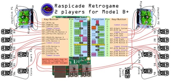
2.) PiPlay comes with the retrogame program which runs in the background and converts button presses to keyboard presses so games can be controlled from the keypad and buttons on the Lynx. The original came from Adafruithere but there's an improved version here by Ian57 which I used and which allows a greater combination of key presses.
3.) Game ROMs and game software. I can't direct you to them for copyright reasons but a quick Google will yield a cornucopia of great games for whatever platforms you want.
Step 3: Remove The Old Lynx Components
A good visual guide on how to take out the components is from MrSiggler and is here. Below are the steps from that guide which we're interested in.
1.) Turn the Lynx over, remove the plastic grips (they're just glued on and can be reattached later).
2.) Unscrew the screws and remove the back.
3.) Remove the screw from the battery compartment and gently lift the main board to allow the battery compartment to be removed.
4.) Remove the ribbon cable (aka flexible printed cable or FPC) by lifting the connector bar and removing the ribbon. Be very careful *NOT* to just pull the ribbon out as it will scrape off the connector printing and ruin the FPC.
5.) Unclip the speaker cable from the main board and remove the speaker itself from the case. You can use a knife to pop it out from its housing. It will be replaced into the housing once we've built the whole circuit and we're ready to insert everything back into the case.
6.) Unscrew the old screen from the front panel.
7.) If you like you can try to desolder the FPC connector from the main Lynx board. As mentioned above I tried this, failed miserably and had to order more FPC connectors to replace it. The pictures above show what the board looked like and the piece itself after I had messed it up. But a replacement doesn't cost much.
All you should have left now is the FPC nicely in place in the front of the case under its housing, the speaker removed from the housing for later use, the back of the case which is empty and the battery compartment which we probably won't need again as it doesn't fit back in after we've put the Pi etc. inside.
Now we're ready to start building the circuit.
Step 4: Connect the New Components – Battery and Power Boost
1.) The battery will connect to the Powerboost board via the JST connector.
2.) Solder the on/off button to the EN and GND pins on the board. After you've done this you might want to connect the battery and test the on/off button. If it's all working the LEDs on the PB board will switch on and off.
3.) The + and – pins at the head of the board are where the other components will be soldered to i.e. the amplifier, the LCD and the PI.
PI – Solder pin 2 from the PI to the -ive pin on the Powerboost board. Solder pin 6 from the PI to the +ive pin on the Powerboost board.
Amplifier – Solder the VCC pin from the amp board to the +ive pin on the Powerboost. Solder the GND pin from the amp board to the -ive pin on the Powerboost.
LCD – Splice the power lead from the LCD to another wire to increase the available length and solder that to the +ive pin on the Powerboost. The wire is normally colored red but check the specs of you monitor to make sure. Splice the ground lead from the LCD to the -ive pin on the Powerboost via an extra wire. The wire is normally colored black but check the specs of you monitor to make sure.
For more detail: Raspberry Pi Arcade Game Emulator in an Atari Lynx


