
Hello their ”young” follower,
in this projects of mine I've will be telling you about one of my little inventions and in return i would like you to hit the vote button for me in the ”contents” tab for more interesting projects and ideas.
‘‘my life story”
I've spent all my life doing project like this since the day I realised my talent in creating electronics + gadgets. the reason I'm creating these projects is because i want to inspire people to get up from their bed's and create ANYTHING because it doesn't mater who YOU ARE.
Step 1: Step:1 connecting the LCD
so for the next step and further on I suggest you to pay attention closely because for a average person like me some part may seem quite a challenge or a bit of difficulty, you may also need to do a little research if you haven't got a clue about what I' showing you. If you got ANY questions please comment bellow. FYI i will reply as soon as possible.
Connecting an LCD
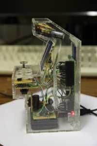
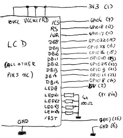
So, I got the Raspberry Pi and I want to do some programming work for it. Why not dive into kernel development? I still had a nice framebuffer module for intelligent displays from my SPI-controlled TFT display. I also had a 2.4″ LCD with an ILI9325 controller configurable to do 8-bit transfers. The 8-bit transfer mode was awesome, because it meant I could directly connect it to the GPIOs of the P1 header of the Raspberry Pi. That made the hardware really simple, and also much quicker because the data wouldn't have to be serialized first. As you can see, there's not much to it. Most IO-pins are directly connected. To save some I/O, the /rd-pin is permanently tied to Vcc because it's not necessary to read from the display. There are 4 resistors for the backlight, and that is it. The pin numbers for the LCD seem to differ from datasheet to datasheet, by the way: if the data pin numbers on your LCD go up to DB17, you'll need to connect the GPIO to DB10-17 instead of DB8-15. Notice the touchscreen isn't connected: it wouldn't have much use on a mini arcade case, and would require extra hardware to get working because the RPi doesn't have integrated AD-converters. I later actually removed the touchscreen from the display to get a clearer image. There's one more hardware thing that needs to happen. The LCD as I bought it has a 16-bit interface, which needs too many pins to connect it directly to the Raspberry Pi. To make it talk over just 8 of the 16 datalines, you need to move a jumper resistor from J1 to J2. The jumper resistor is 0402, but a simple wire works too:
Step 2: Step 2: case
so after you done all the soldering and connections to the raspberry pi. BRILLIANT. you are ready for the next stage. which is the casing.well because i'm so nice i decided to get the things you need to get this design done. if you dont like what i've done you can modify it if you want to or need to.BEFORE you move a muscle! you need to paper or card model the case to check or mistakes.
For more detail: Raspberry pi arcade project