Plugging the laser module on Arduino
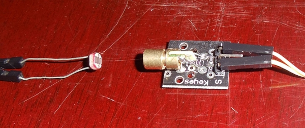
Isn’t easy to plug a module when you have no datasheet or some wiring schemes, the chances are that you’ll probably burn it if you provide a current greater than the supported. The module I have was bought on the DX.com and it came with 3 pins, “-” mark, “S” mark and a middle pin without any mark, I assumed that the “S” meant “Signal” and the “-” is the GND pin so I started plugging it on the Arduino pin 14 with a 440 ohm resistor and later I discovered that a 100 ohm resistor was giving the best bright laser without burning it; my advice is to not connect direct any of these modules without a resistor to limit the current, otherwise you’ll end up burning the diode.
In order to test the laser, I just uploaded this program to Arduino, it just blinks the laser module:
|
1
2 3 4 5 6 7 8 9 10 11 12 13 14 15 |
int laserPin = 12; void setup() void loop() |
Look Ma, no ADC !
Since Raspberry Pi doesn’t comes with an Analog-to-digital converter (ADC) like Arduino, connecting a LDR to its GPIOs pins is a little tricky (when you don’t have an Gertboard). The traditional approach is to use a capacitor and then time its charging according to the LDR resistance, this isn’t a precise measure, but it works good for most applications. What I’m going to do here is another approach, since I just want to measure if there is a laser light present or not (I’m not interested on the light energy), I don’t need to time the capacitor charging.
The first step was to measure the resistance that the LDR creates when the laser light is present, to do that I turned the pin 12 to HIGH on the Arduino and then measured the resistance on the LDR with the multimeter:
And the measure was roughly 200 ohms, when the laser wasn’t pointing to the LDR (even with the day light) the resistance was around the 2k ohm. Now we know that we have to build a circuit that is will use the interval of 0 ohms to 400 ohms (a good margin) as the threshold to activate/deactivate the GPIO pin of the Raspberry Pi.
The challenge now was how to create a circuit that would set the GPIO pin of the Raspberry Pi according to a defined threshold. It turns out that with the help of Oli Graser (see more about the circuit here), I discovered that you can create a voltage sigmoid with a voltage divider circuit outputing to a general transistor, and this is really awesome, can you imagine something like a logistic regression built in hardware ? Absolutely interesting.
Voltage divider and the “sigmoid” circuit
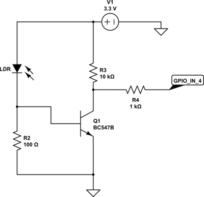
And here is the schematics of the voltage divider using the transistor as control of the GPIO pin:
The first part of this circuit is the LDR and the R2 resistor, together they work as voltage divider, when the laser is off, the LDR resistance is very high and then the voltage that goes to the base of the transistor Q1 (I used a BC547B) is very low, making the GPIO pin 4 state to go HIGH, when the laser is on, the LDR resistance is very low and the voltage going to the base of the transistor is enough to activate the circuit and makes the GPIO ping 4 state to go LOW since the the current will flow to the path of less resistance, which is to the GND.
For more detail: Raspberry Pi & Arduino a laser pointer communication and a LDR voltage sigmoid


