
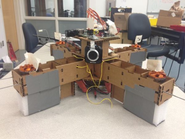
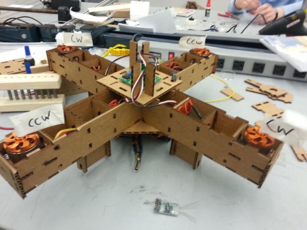
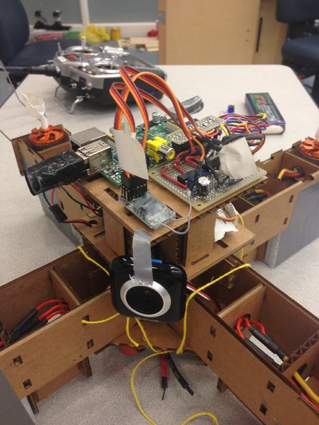
This is an autonomous cardboard quadcopter driven by a Raspberry Pi. It is capable of wireless communication as well as well as real time image processing via camera.
This quadcopter was built by 4 sophomores at Olin College of engineering for a class called Principles of Engineering.
For more information see http://poe.olin.edu/poe2013/s_engr2210-quadcopter/ .
Raspberry pi based Drone Quadricopter
Raspberry pi based Drone Quadricopter
Step 1: Materials
Cardboard from the recycling bin,
The sheet we we used was 32″x20″ with a thickness off around 4.1mm. A large clean box should do.
Motors from Hobby King, 4x + Propeller clamps,
We used Turnigy D3530/14 1100KV Brushless Outrunner Motor at $14.56 each. Our motors also came with propeller clamps which allowed us to easily connect our propellers to the motors.
Electronic Speed Controllers (ESC) from Hobby King, 4x,
We used TURNIGY Plush 18 amp Speed Controller at $11.90 each.
Propellers from GWS props, 2x counterclockwise rotating, 2x clockwise
We used 3 bladed 8x4x3 GWS props at $2.00 each.
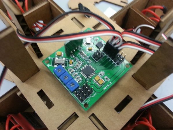
Flight Controller from Hobby King, 1x
We used HobbyKing Multi-Rotor Control Board V2.1 at $12.99
Flight Controller Mounting Pads from Hobby King,
We got a pack of Gyro / Flight Controller Mounting Pad at $1.99 but one can also use double sided tape.
RC Receiver from amazon.com, 1x,
We got a CSRC-RX3000 Spektrum DSM2 Compatible 2.4Ghz 6-Ch Receiver on sale for $9.99. Any 5 or more channel receiver will do though.
Foam block, cut into 4 2 inch by 4 inch chunks,
Used for a more durable landing.
Cyanoacrylate based glue,
Anything will work, the thicker the glue, the easier it is to work with. We used something along the lines of this.
Tape,
We used duct tape for mounting the foam landing pads as well as for low force attachment of electronics.
Nuts and bolts, 16x sets of 1 nut and 1 bolt,
Washers can be used when directly bolting to cardboard, but we found that you did not really need them. We used 4-40 x 5/8 inch nuts and matching bolts.
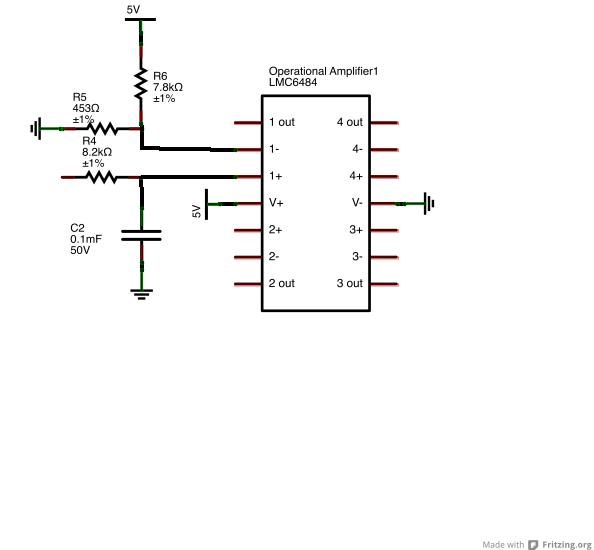
0.1mF capacitor, 1x
Used in the low pass filter before the Schmitt trigger.
7.87kΩ resistor, 1x
Used in the voltage divider.
8.2kΩ resistor, 1x
Used in the low pass filter.
453Ω resistor, 1x
Used in the voltage divider.
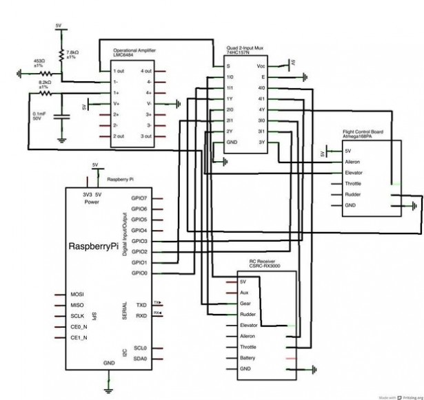
Operational Amplifier (LMC6484) , 1x
Used to create the Schmitt trigger.
Quad 2-Input Mux (74HC157N) from Digikey, 1x
Used to switch between the RC receiver and Raspberry Pi signal.
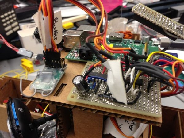
Section of perf-board
Used to solder the entire switch circuit in a condensed form for the quadcopter.
Battery from Hobby King, 1x
We used Turnigy nano-tech 3300mah 3S 25~50C Lipo Pack at $26.72.
Battery indicator, 1x
This device changes color and beeps if the batter is at low voltage. This is a must have if you don't want to keep breaking batteries. We used a 3 Cell Hobby King Battery Monitor at $3.99.
BEC from Hobby King, 1x,
This is used to power the Raspberry Pi. We used HobbyKing Micro UBEC 3A / 5v at $3.77.
Servo Connectors, female to female from Hobby King, 4x,
We got a pack of 5 female female from hobby king at $1.65 that we cut in half.
Power Wire, 2x 6 inches high current pieces,
We used 10 AWG red and black that can be bought from hobby king at for $2.99 a meter.
4mm Bullet Connectors, at least 1 male and 1 female.
Casing is nice, so we would suggest HXT 4mm Gold Connector w/ Protector at $3.64.
3.5mm Bullet Connectors, at least 12x
Available in packs of 10 from hobby king for $1.59.
Raspberry Pi, 1x,
We used one of the older model B with 256mb of ram for $35.00. A model A would work and probably better for $25. They are currently hard to buy, you could place an order from a vendor on their site and wait a few months, or just get one from Amazon.
Web Camera from amazon.com, 1x,
Really any usb webcam with linux support will work. We used Microsoft-LifeCam-VX-5000 for $12.74.
Wifi Card from amazon.com, 1x,
Any linux supported wifi card should work. We used this card at $13.06.
SD Card, 1x,
We used a 16gb card from amazon at $11.52.
Micro usb cable, 1x,
It does not need to be long, we used a six inch cable at $3.09.
Off-Board
AVR Programming device one from Hobby King, 1x
We first got USBasp AVR Programming Device for ATMEL processors at $4.95. Our board was defective, so we ended up using a Atmel AVRISP mkII In-System Programmer at $34
RC Transmitter, 1x
We used the highly overkill DX8 8CH Transmitter at $429.99. All you really need is 5 or more channels.
3 cell Lipo Battery Charger + Power supply, 1x,
Some way to charge your battery.
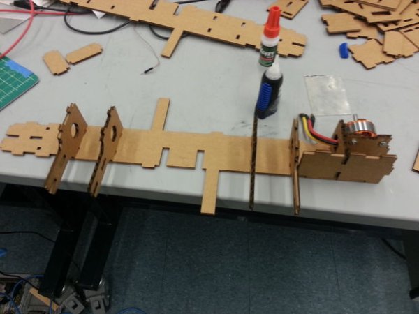
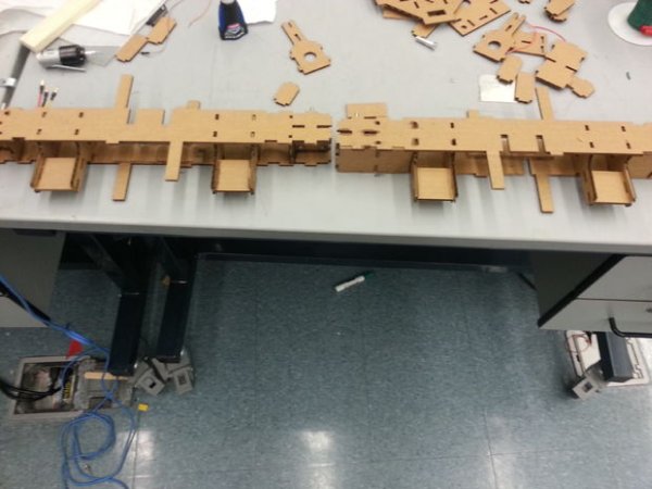
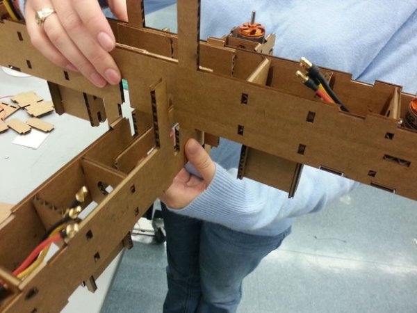
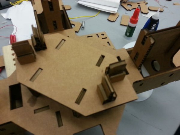
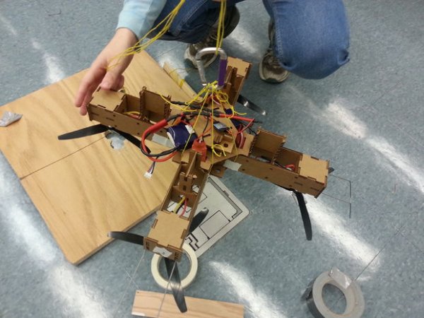
Step 2: Cut and Assemble Frame
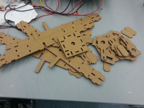
The entire frame is assembled from laser cut cardboard. Our team was able to fit all of the required parts onto one sheet that could fit in the laser cutter. When designing this sheet, great care was taken to align the parts to match the correlations in the cardboard. If you would like to make your own sheet, you can use our cad located here.
Otherwise you can use our cutsheet attached.
We used a thick Cyanoacrylate based glue to do all of our connections. This gave us both strength and quick dry times.
Be careful when assembling the arms and read through the directions before you start.
http://www.instructables.com/files/orig/FA2/1YZ2/HAGQ72MY/FA21YZ2HAGQ72MY.pdf
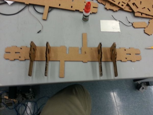
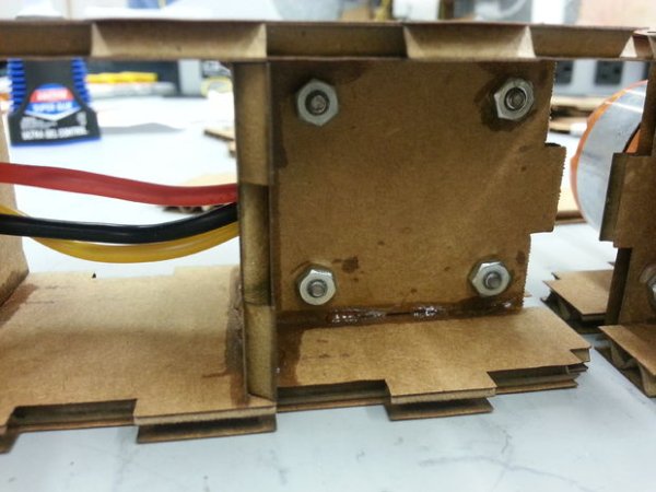
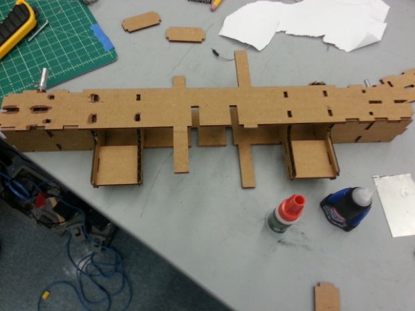
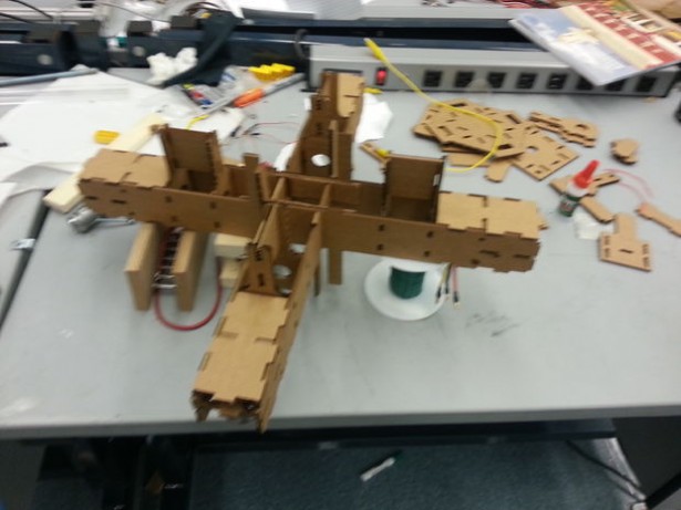
Step 3: Frame
Step 4:
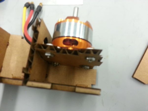
Bolt motors to cardboard motor mount.
Step 5:
Step 6:
Assemble the other side of arm.
Step 7:
Place other arm plate onto the assembly.
Step 8:
Step 9:
Slide arms together
Step 10:
Step 11:
Step 12:
Step 13:
Step 14: Add on Propeller guards
Step 15:
Step 16: Make the power distributor
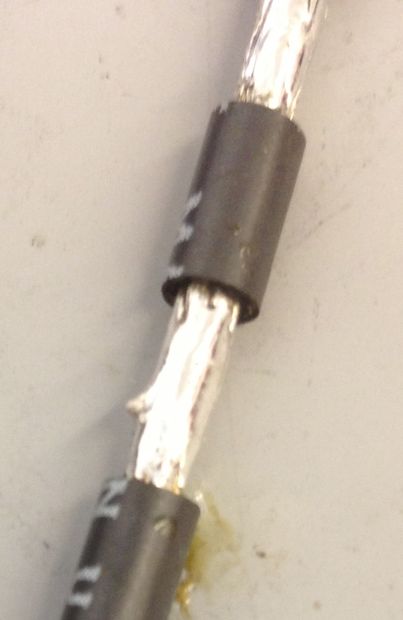
Take each section of thick, high amperage wire and use a razor blade to carefully strip five sections of about an 2 cm that are about 2.5 cm apart down the wire.
Strip the end of each wire about 1 cm and tin them both.
Make a jig by drilling holes to match the sizes of the battery connectors, so that the battery connectors plug into it nicely and don't move around. This video shows the process well. http://www.youtube.com/watch?v=MnldHRtjre8
Tin the cups of the connectors by melting solder into them until they are almost full or solder.
Let the battery connectors cool for a little while after they have been tinned.
Melt the solder in the battery connectors a second time and insert the end of the battery wire into the molten solder.
Remove the soldering iron and hold the wire motionless for about a minute or until the solder is completely re-hardened.
Heat shrink over these joints so that you won't be able to short the battery.
Tin the other exposed sections of wire carefully with your soldering iron set on high heat.
Step 17:
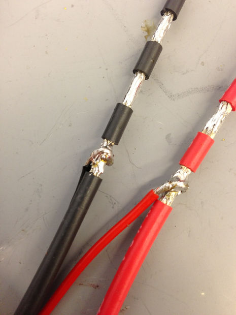
Tin the ends of the motor speed controller and BEC wires that you will be connecting to the main power wire.
Wrap the ends of the motor speed controller wires around the stripped and tined sections of the high amperage wire using pliers.
Solder the two wires together ensuring that a good connection is made.
Place heat shrink over this new joint and shrink it so that the new joint is insulated and protected.
Solder the next motor speed controller to the power distribution wire and heat shrink it. Repeat this until all of the motor speed controllers and the BEC are soldered to both the power and ground wires and heat shrinked.
Heat Shrink over the ends of both wires that do not contain the connectors so that these ends do not short.
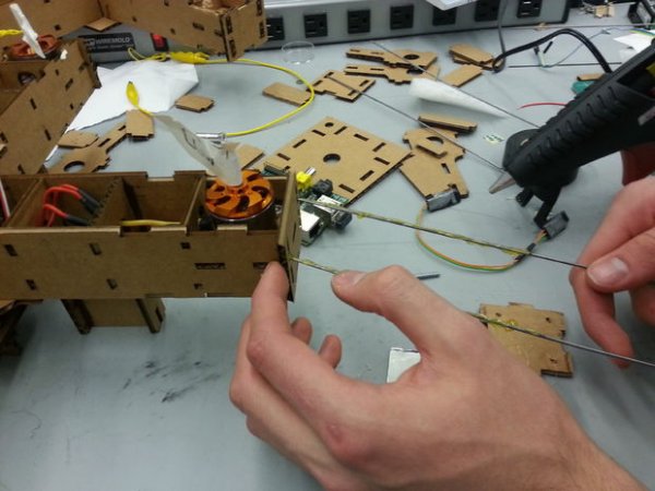
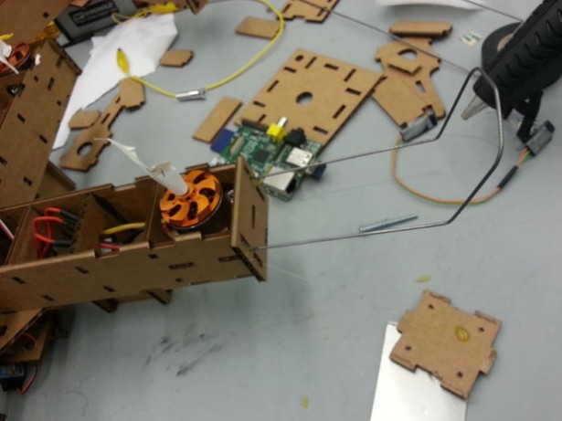
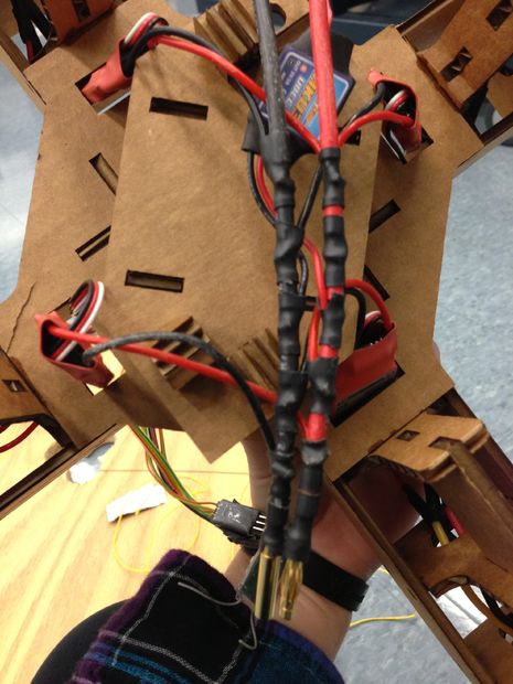
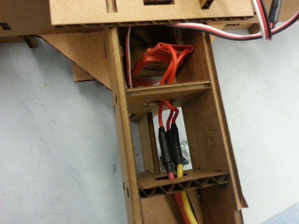
Step 18: Integrate Electronics
Step 19:
Step 20:
Step 21:
Step 22: Electrical System
Step 23: Test the Switch
Step 24:
Step 25: Setting Up the Pi
Step 26: Tips for Writing Autonomous Code
Always write code on a computer. Due to the number of libraries we are using and the speed of the Raspberry Pi compile times are quite painful to debug with. In general, all code can be written on the computer, tested on the computer, and then uploaded to the Pi. Another more extreme option to minimize recompiles is to place all of the configuration values in an external file that can be changed at runtime.
As with all programming, start small and test. At least in our experience, the code can get quite complex very quickly and it helped a lot to make small tests.
Test your code! When writing image based autonomous code, its generally a good idea to run automated tests on your code. These tests take your code, and would run them in various virtual environments on a simulated quadcopter that behaves like the actual one. For our project we where not doing very complicated autonomy so we opted not to create this simulated environment. If your plan is to add more, we would strongly recommend creating a testing environment such as this.
If you want a starting point, see our code: Our codebase is located at https://github.com/lukemetz/PiQuopter-Vision.
Step 27: Program the Flight Controller
The first thing we did when we got out flight controller was to reprogram it to use the kapteinkuk xcopter kk firmware. To do this, we used the kkMulticopter Flashtool. We went with the xwing configuration because we have a camera on board. The camera look forward if it is placed between two arms and not have to look through propeller blades.
To finish setting up the flight controller, follow the kk Quad x setup guide located at RCExplorer. This guide walks you through testing and configuring the ESC and the flight controller.
Step 28: Attach the Top Layer of Electronics and Camera
Step 29: Bind the Transmitter to The RC Receiver
Step 30: Tunning and Stabilization
Tunning our quad copter was quite difficult for us. To begin with, we neutral the potentiometers. Move the first and third pot to 50% and the second pot to 0%. In the firmware we are using the second pot is unused. To begin with, we tied down our quadcopter such that it could not fly away. We then used the RC controllers trim values to trim it level. This step takes a lot of time and tinkering with controls.
Once the copter is more or less level, use the first pot to adjust roll and pitch gains and then tune the 3rd pot until the copter flies straight.
Once you have configured your quadcopter, you are going to want to scope the output of the RC receiver such that you can emulate the tunning in the autonomous code.
While doing this step, we strongly recommend you tie down your quadcopter to prevent it from getting out of control. Never turn off the controller while the battery is plugged in, as the default mode for the control board is all motors full on.