
Binary clocks show the time in an unconventional format. They display the hours, minutes and sometimes even seconds as numbers represented in the binary numeral system. Binary clocks and binary watches have grown quite popular today. More and more people work in IT and become familiar with the binary numbers, the native language of our computers. Most who understand binary notation, consider it clean, simple and elegant, so it’s only natural that they perceive binary clocks and watches as cool gadgets.
Once you get the hang of it, reading binary watches is very easy. All you have to understand is that the clocks show binary digits (bits) and that each binary digit represents a factor of two and that you have to add together all the factors which are set (on). For example, 101111 = 1*2^5 + 0*2^4 + 1*2^3 + 1*2^2 + 1*2^1 + 1*2^0 = 1*32 + 0*16 + 1*8 + 1*4 + 1*2 + 1*1 = 32 + 0 + 8 + 4 + 2 + 1 = 47. This might seem a bit complicated at first for the untrained brain, but a little practice will make you read these combinations almost instantly.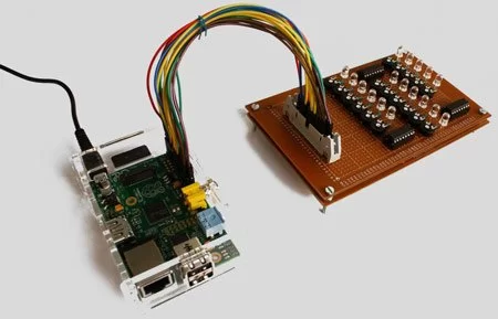
The binary digits can only have two states: 0 and 1. This means that a binary watch must display the time using some things that also have two states. And what is more suitable for such a purpose than a light? A light is either on (1) or off (0). To be honest, I’ve never seen a binary watch using anything else than a light for digits, although I’m sure that people’s creativity is endless and there are some unusual devices out there, but the vast majority of the binary clocks just rely on LEDs for displaying the time. LEDs are very practical for this purpose because they draw very little current, their light is strong enough but not too strong, they come in many different colors, they turn on and off very fast (unlike conventional light bulbs) and they are cheap.
Not so many years ago it was very hard to buy a binary clock or watch. If you wanted one, you had to make your own. Today the situation is different: they are available in large quantities and in many shapes and sizes, from wrist watches to wall clocks. Unfortunately most of them are not 100% binary clocks. Instead they are pseudo-binary clocks, which mix the binary numeral system with the decimal numeral system. For example a real binary clock would display 47 as 101111, while a pseudo-binary clock displays it in two groups of digits: 100 (4) and 111 (7), which means that you have to multiply the value of the first group by 10 and add the value of the second group to it. The market is full of such not real binary clocks. It’s hard for me to understand why people buy them. I mean, if you want binary, why not go for real binary? I have a pseudo-binary wrist watch myself, but I’m just not satisfied with it, so I decided to make a real binary clock to keep in my room. This is how the first prototype turned out:
In the following I am going to show you how to make a binary LED clock which is driven by a Raspberry Pi. In other words, we’ll make a circuit with is able to light up some LEDs in any combination and a Raspberry Pi will be responsible for keeping the time and instructing the circuit which LED to tun on and which to turn off. If you are thinking at this moment that using a Raspberry Pi as the brain of the binary clock is a little exaggerated, you are right. There are many simple circuits that can do the job, the Raspberry Pi is a full general usage computer, using it for keeping time and driving some LEDs is just so much below its capabilities. It’s like shooting a bird with a canon. True. But it’s a great learning project, good practice to get accustomed with using the Raspberry Pi’s GPIO pins to drive custom hardware.
Let’s design our clock in theory first. If we make a clock that displays the time in 24-hour format, the maximum possible value of the hour is 23, which is less than 32 (2^5). This means that we will need 5 LEDs to display the hours. The maximum value for both the minutes and seconds is 59, which is less than 64 (2^6), so we are going to need 6 LEDs for the minutes and for the seconds. That means a total of 17 LEDs used as binary digits on our clock. Now, it may not strike you at first as such, but the fact that we need 17 LEDs, and not 18 or more, is an extremely lucky coincidence. That is because the Raspberry Pi has a total of 17 programmable GPIO pins available on the P1 header, which we can use to drive our LEDs. Many will argue that using all available pins is a terrible waste because there are techniques to drive 17 LEDs using as little as 3 GPIO pins. True. But we want to keep things simple. We don’t want to go into the more complicated stuff, like serial communication and shift registers, multiplexing, charlieplexing and so on. Let’s stick to the basics with this project by controlling each LED with a separate GPIO pin.
One more thing to keep in mind is that the Raspberry Pi can safely supply a maximum of 16 mA per GPIO pin and 51 mA in total on all pins. Our clock would light up all LEDs simultaneously when the hour is 63, the minute is 31 and the seconds are 31. That is an invalid time value, so it should never happen, unless the controlling software messes things up because of a bug. Let’s plan for the worst though, and design our clock to give 3 mA of current to each LED (because 17 * 3 = 51). Although most 5 mm LEDs (which we will use) are rated at 20 mA, I have found that they give more than sufficient light even at 1 mA, especially the super bright ones. We are going to choose the resistor values in a way that will supply 3 mA of current to each of our LEDs (blue, white and orange). If you want to use different LEDs or wish to have a different amount of current running through them, use the LED calculator to obtain the appropriate resistor values. Optionally you can add variable resistors connected in series with the normal resistors. This will allow you to control the amount of drawn current and the brightness of the LEDs at any time, after the circuit is done. A good value for the variable resistors may be 10 kOhm, but you can even use higher values and the LEDs will still be bright enough.
Using resistors which will limit the current through the LEDs to 3 mA will guarantee that we do not exceed the maximum ratings of the GPIO pins and we’ll not damage them. This means in theory that we could simply connect the LEDs to the appropriate programmable GPIO pins directly through the resistors. You will notice, however, that in our design we use ULN2003 or ULN2803 integrated circuits to isolate the currents going through the LEDs from the currents coming from the programmable GPIO pins. We do this for the following reasons:
-
- We want to make it theoretically possible to use other LEDs or lights with the clock, which need more than 3 mA of current each. Isolating the signal circuit from the light circuit using the ULN2003/ULN2803 ICs makes this possible. This design allows you to give each of the LEDs 20 mA of current, as specified by the manufacturers, although it’s probably a waste of current in most cases. If you exceed the ratings of the GPIO pins, you will have to use a 5V external power supply for giving current to the load circuit. Otherwise you can connect the load circuit too to the 5V power supply pin of the Raspberry Pi.
- We want to draw the current from the 5V power supply pin of the Raspberry Pi. If we connect the LEDs directly to the programmable GPIO pins, that means that the LEDs will get 3.3V instead. This may be possible, but the resistor values will need to be recalculated. Generally, the 5V power pin is more suitable for our purposes because it’s able to give off more current.
- All in all, it’s a good idea to decouple the load circuit from the signal circuit because it offers better protection to the Raspberry Pi. It’s safer. You don’t want to risk your Pi, do you?

Required parts
- 5x LEDs for the hours (I have used blue super bright 5 mm LEDs).
- 6x LEDs for the minutes (I have used orange super bright 5 mm LEDs).
- 6x LEDs for the seconds (I have used white super bright 5 mm LEDs).
- 5x 680 Ohm resistors for the blue LEDs with 3.3 V voltage drop.
- 6x 1 kOhm resistors for the orange LEDs with 2V voltage drop.
- 6x 680 Ohm resistors for the white LEDs with 3.3V voltage drop.
- (Optional) 17x 10 kOhm variable resistors, one for each LED, to be able to control their brightness (and the drawn current) at any time.
- 3x ULN2003 or ULN2803 ICs for switching the LEDs with sginals from the Pi.
- (Optional) 3 sockets for the ICs to avoid their direct soldering onto the board.
- 1x 26-pin male IDC connector.
- 1x 26-pin female-female IDC ribbon cable to connect the binary LED clock to the Raspberry Pi. 19 pieces of female-female jumper wires can also be used instead.
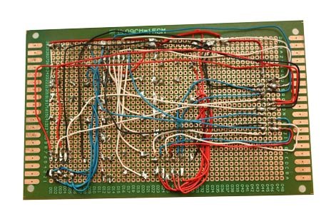
- 1x stripboard (breadboard) for soldering all the components onto it.
- Insulated wire (preferably in many colors) for connections between components on the back of the board.
Connections
1. Connect the 5V power supply pin of the Raspberry Pi to the anode (positive leg) of each LED. To identify the 5V power supply pin, read this.
For more detail: Raspberry Pi Binary LED Clock