
Bluetooth Low Energy (aka BLE/Bluetooth 4.0/Bluetooth Smart) is the most recent incarnation of Bluetooth technology developed by the Bluetooth SIG (the organization that maintains the specification). This communication protocol is designed for applications where data needs to be transferred in small amounts at relatively low speed while consuming low amounts of power (e.g., heart rate monitor, step counter, wireless keyboard). This latest version of the protocol is not compatible with its predecessor (Bluetooth classic), as an upside, long gone are the days where pairing devices was necessary!
The goal of this Instructable is to demonstrate how you can setup your Raspberry Pi to control RGB LEDs from a Bluetooth Low Energy (BLE) device nearby. Specifically, we'll be using the RFduino microcontroller, which has a built-in BLE module. We'll easily program the microcontroller to listen to messages sent by the Pi and control the LED color accordingly.
Let's get started!![]()
Step 1: List of Materials
In this Instructable we'll be using the following materials:
Materials:
1 x Raspberry Pi 2 with a 5V USB Power Supply
1 x 8GB MicroSD Card
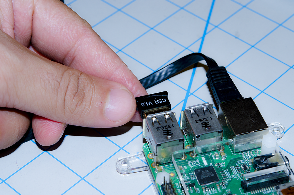
1 x USB Bluetooth 4.0 Adapter – Most USB BLE adapters are RPi compatible (use CSR chip); check the compatibility here.
1 x RFduino Essentials Kit (2 pieces)
1 x 8mm PL9823-F8 (NeoPixels) RGB LED – Through-Hole, Diffused
Tools (Optional):
Step 2: System Overview
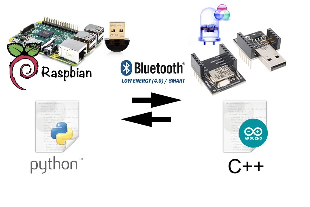
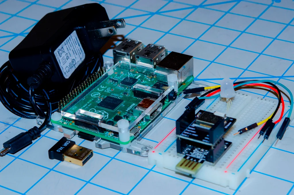
In order to control an RGB LED wirelessly we'll be using a few different hardware and software components that we'll outline here.
Raspberry Pi
We'll be making use of a Raspberry Pi, a single-board computer running the Raspbian distribution of the Linux Operating System. Because the Pi doesn't have a native BLE interface, we'll connect a USB Bluetooth LE adapter to it. A script that we'll write using the Python programming language will let us send commands BLE via the USB adapter. The commands sent over BLE will be received by a separate microcontroller via its own BLE interface (RFduino).
The list of components that will be used on this side of things is:
- Raspberry Pi (hardware)
- USB BLE Adapter (hardware)
- Raspbian (software; Operating System)
- Bluez Bluetooth stack for Linux (software; libraries, tools)
- Python Script (software; user code)
RFduino
To control an RGB LED we'll use the RFduino microcontroller connected to it on a solderless breadboard. The tiny-sized RFduino can be programmed over USB from any computer capable of running the Arduino IDE. In this case we'll use a Mac laptop to write code in C++ using version 1.6.4 of the Arduino IDE. We'll use the same IDE to upload the code to the RFduino. Once the code is running on the RFduino we'll go back to the Pi and run the Python script to change the color of the RGB LED.
The list of components that will be used on this side of things is:
- RFduino (hardware)
- RGB LED (hardware)
- Arduino IDE (software; program)
- C++ firmare (software; user code)
Step 3: Configuring your Raspberry Pi to use Bluetooth LE
Currently, Bluetooth Low Energy (BLE) is not well supported by the standard Raspberry Pi distributions, thus some additional work is required to get it working. We've put together a comprehensive guid on how to get started in a previous Instructable:
http://www.instructables.com/id/Control-Bluetooth-LE-Devices-From-A-Raspberry-Pi/
Step 4: Configuring the RFduino in the Arduino IDE
After configuring the Raspberry Pi to use BLE, we're ready to load a program to our RFduino. But, first we need to prepare our computer to recognize the RFduino boards.
At the time of this writing the following instructions have been tested in the latest version of the Arduino IDE (1.6.5). With your RFduino disconnected from the computer where you'll be using the Arduino IDE to program the RFduino.
- Download and install Arduino IDE v1.6.5 or newer for your Operating System (OSX, Windows, or Linux)
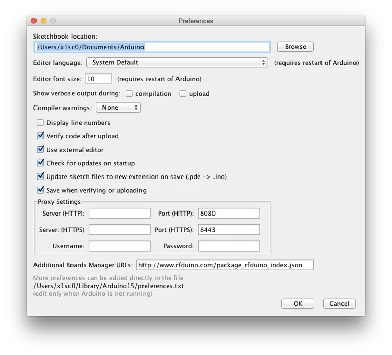
- Edit the Arduino IDE Preferences/Settings, and under Additional Board Manager URLs add:
http://rfduino.com/package_rfduino_index.json - Navigate to Tools > Board > Board Manager and scroll down to RFduino Boards by RFduino. Click and select install the RFduino library.
- Double check that “RFduino” is one of the entries now under Tools > Board
- Connect the RFduino DIP Module to the RFduino USB Shield by matching the Pinouts. Then proceed to connect it to the computer's USB port.
- Restart the Arduino IDE and the connected RFduino should be available under Tools > Port otherwise you may need to install the FTDI drivers for your Operating System.
Having trouble? Consult the comprehensive Quick Start guide by the RFduino creators.
Now that we're able to program the RFduino, we can write the code that we'll upload to it!
Step 5: Firmware for the RFduino: Receiving Messages
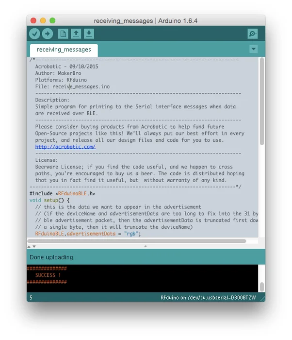
The goal for the program on the RFduino is to receive messages from the Pi, process them, and use the sent values to change the colors of the RGB LED. We'll break down the development of the code into these 3 tasks.
Receiving Messages
The first step is to write the code that will allow the RFduino to receive messages from the Pi or any other BLE-capable device. The first thing we'll setup is to broadcast under the id “My BLE LED”, and to idle in low-power mode while a message is received.
As with every program written in the Arduino IDE, we want to define the setup() and loop() functions:
void setup() {
// this is the data we want to appear in the advertisement
RFduinoBLE.advertisementData = “My BLE LED”;
// Start the BLE stack
RFduinoBLE.begin();
}
void loop() {
// Switch to lower power mode
RFduino_ULPDelay(INFINITE);
}
The RFduino functions we've called are standard for any piece of code that we write using this neat board. In order to receive messages, we'll add the following 3 functions:
void RFduinoBLE_onConnect() {
// Debug message printed to Serial interface
Serial.println(“RFduino connected”);
}
void RFduinoBLE_onDisconnect() {
// Debug message printed to Serial interface
Serial.println(“RFduino disconnected”);
}
void RFduinoBLE_onReceive(char *data, int len) {
// Debug message printed to Serial interface
Serial.println(“Data received: “);
for(int i=0;i Serial.print(data[i]);
Serial.println();
Serial.println(data);
}
Now that we've examined the code, we're ready to upload it to our RFduino. To do this, connect the RFduino DIP Module and the RFduino USB Shield. Then proceed to connect the connected boards to the USB port of your computer.
After uploading this simple program to the RFduino, we can test the communication from/to the Raspberry Pi!
Step 6: Writing Data Interactively With Gatttool (Raspberry Pi)
With the Raspberry Pi and RFduino ready to go, we can go ahead and open a Terminal Window on the Pi and make sure that the RFduino is powered.
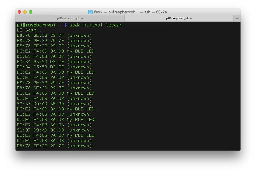
The first thing we do is to scan for nearby BLE devices by entering the command:
sudo hcitool lescan
We'll see that the output will contain an entry for our RFduino, in our case it reads:
DC:E2:F4:0B:3A:03 My BLE LED
Where the first set of alphanumeric (hex) characters corresponds to the MAC address of our RFduino, and the string “My BLE LED” is the device name we assigned to it. Now that we have the MAC address, we can use it to write data to the RFduino.
For this step we want to open a Serial Monitor window on the computer where the RFduino is connected. This will allow us to see the debug statements we programmed. Next, we go back to the Terminal Window on the Pi and enter:
sudo gatttool -b DC:E2:F4:0B:3A:03 -t random -I
Note: remember to change the Mac address for your own, and that the last letter of the command is a capital “i”.
As seen in our previous Instructable, this allows us to send/receive commands interactively. The next steps are to issue the commands to connect, and write data to the RFduino while keeping an eye on the Serial Monitor:
[DC:E2:F4:0B:3A:03][LE]> connect
Note: After entering the command “connect” you should see a “Connection successful”message on the Terminal Window and a “RFduino connected” on the Serial Monitor.
Next, we can send some data to the characteristic handle (0x0011) where the RFduino listens to incoming messages:
[DC:E2:F4:0B:3A:03][LE]> char-write-req 0x0011 5B48454C4C4F5D
If we look at the Serial Monitor we can see how the messages are received:
Data received:
91726976767993
[HELLO]
This shows that the character array data has a length equal to the number of bytes we send. In our case, the first byte is “5B” whose decimal equivalent is “91” and corresponds to the character “[“. Our second byte is “48” whose decimal equivalent is “72” and corresponds to the character “H”.
Knowing this, we can now start sending commands to control the brightness and color of an RGB LED!
Step 7: Building and Testing an RGB LED Circuit With RFduino
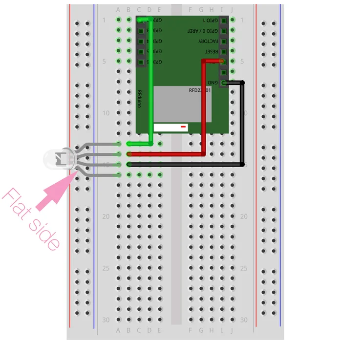
We are now ready to wire a very simple circuit using our RGB LED. Unlike regular RGB LEDs where each pin is physically connected to either the positive or negative terminal of a Red, Green, and LED, these PL9823-F8(aka NeoPixels)are ‘smart' LEDs that contain additional circuitry inside allowing them to receive and send data using a custom 1-wire communication protocol. For this reason we wire it a little differently than to what you may be accustomed, so double-check the wiring diagram!
First, make sure you disconnect the RFduino Module and Shield from the USB port of the computer! Then proceed to follow the wiring diagram. Once its done, go ahead and connect it to the computer running the Arduino IDE and ensure that everything is in order as described in the previous step.
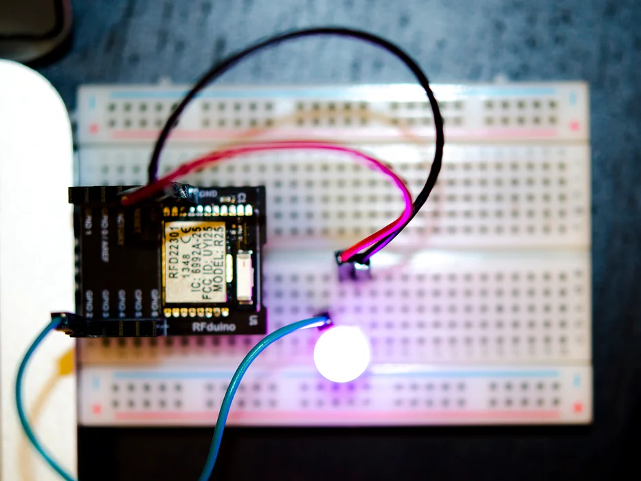
Note: once you apply power to the RFduino you might see the RGB LED turn on to a blue-ish color; this is ok!
Second, we need to download a library that will allow us to use these LEDs with the RFduino board. We've written our own specifically for the RFduino, which is based on the wonderful NeoPixels library written by Adafruit.
The library is available at https://github.com/acrobotic/Ai_RFDlib_WS2812/ and if you're not familiar with Git/Github, simply click download on the bottom right side of the page.
Then, you can simply use the Arduino IDE to import the downloaded zipped library by navigating to Sketch > Include Library > Add .ZIP Library… and selecting the recently downloaded file “Ai_RFDlib_WS2812-master.zip”. Once this is done go open the rainbow example by navigating to File > Examples > Ai_RFDlib_WS2812-master > rainbow and upload it to the RFduino.
Feel free to tweak the rainbow program to experiment with the RGB LED a bit. In the next step we'll be loading the code that will not only receive the messages from the Raspberry Pi, but also set the brightness of the LED!
Step 8: Writing BLE Data Directly From the Terminal (Raspberry Pi)
With the circuit built and tested we're ready to start sending RGB LED brightness/color data from the Raspberry Pi. The first thing to do is ensure that our RFduino is ready to receive data to control the RGB LED. For this we upload the code in the ble_led_control archive using the Arduino IDE.
Once the code is loaded to the RFduino, we can go back to our Raspberry Pi and use the command gatttool that we were using before. However, instead of using the interactive mode, we'll enter complete commands directly. For instance, in order to turn on the Red and Blue LEDs to maximum brightness we use the command:
sudo gatttool -b DC:E2:F4:0B:3A:03 -t random –char-write-req -a 0x0011 -n FF00FF
We're familiar with the first part of the command (sudo gatttool -b DC:E2:F4:0B:3A:03 -t random) as this is what we were using before, however we've gotten rid of the “-I” switch, which is what started the interactive prompt. Instead, we are writing the “–char-write-req” directly using the same handle as before (0x0011). The only thing that has changed is the last value.
On a previous step we saw how the data is sent in bytes, which made it a little tricky when we needed to send character values as we needed to send their HEX representation instead. In this case, we simply want to send 3 values ranging from 0 to 255 that will set the brightness of each LED.
Fortunately, we can use a single byte to represent each value (0 is 0x00, 10 is 0x0A, … 255 is 0xFF). So to send the RGB data so that the Red and the Blue LEDs are set to maximum brightness, we simply send the 3 bytes “FF”, “00”, and “FF”. This should result in a purple/pink color in the RGB LED!
In our final step we'll describe a simple way of making our Raspberry Pi change the colors programmatically using Python!
Attachments

Step 9: Writing BLE Data Programmatically in Python (Raspberry Pi)
In this last step we'll write a script in Python to use the program gatttool programmatically. That means that we'll structure our script in a way that will allow us to use gatttool without having to repeatedly enter commands in the terminal.
The script is fairly straight forward, and can be expanded by you to display different animations of the RGB LED. With the RFduino powered and running the same firmware as in the previous step, we go to our Raspberry Pi and open a Text Editor (e.g., Leafpad).
We'll use it to create our script. We start by entering a couple of function definitions:
MAC = “DC:E2:F4:0B:3A:03”
CHAR = 0x0011
def initialize():
commands.getoutput(‘hciconfig hci0 down')
commands.getoutput(‘hciconfig hci0 up')
print commands.getoutput(‘hciconfig -a')
commands.getoutput(‘killall hcitool')
The initialize() function takes care of configuring the BLE interface. Although we did this already in a previous step, it's not bad to ensure it's available. This function will print the output of the command hciconfig to the Terminal Windowwhere the script is ran.
def sendColor(c):
command = ‘sudo gatttool -t random -b {0} –char-write-req -a {1} -n {2}'.format(MAC, CHAR, c)
p = subprocess.Popen(command.split(), shell=False)
print p.communicate()[0]
The sendColor function takes a 3-byte string and sends it to the device with mac address MAC to the characteristic handle CHAR. You'll need to replace these values with your own values at the beginning of the script.
if __name__ == ‘__main__':
initialize()
sendColor(‘FF0000')
time.sleep(1)
sendColor('00FF00′)
time.sleep(1)
sendColor(‘0000FF')
time.sleep(1)
sendColor(‘000000')
Lastly, when the script is ran it will run the initialize() function once, and then set the color to full-brightness Red, wait 1 second, full-brightness Green, wait 1 second, full-brightness Blue, wait 1 second, and then send a ‘no color' (OFF) command.
Source: Raspberry Pi Bluetooth LE Controller for WS2812B (NeoPixels)